
Instruction Manual


Quick Reference
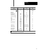
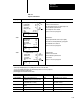
Appendix C
C6
Table C.E
Relay
T
ype Instructions
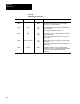
NOTE: You can assign input and output addresses, XXXXX, to any location in the data table, excluding the processor work
areas. The word address is displayed above the instruction and the bit number below it To enter a bit address larger than 5
digits, press [EXPAND ADDR] after the instruction key and then enter the bit address. Use a leading zero if necessary.
Key Symbol Instruction Name 1770-T3 Display Rung Conditions
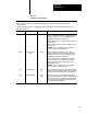
-| |- Examine On XXX
-| |-
XX
When the addressed memory bit is on, the instruction is true.
-| / |- Examine Off XXX
-| / |-
XX
When the addressed memory bit is off, the instruction is true.
-( )- Energize XXX
-( )-
XX
When the rung is true, the addressed memory bit is set.
If the bit controls an output device, that output device
will be on.
1
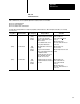
-(L)- Output Latch XXX
-(L)-
ON XX or OFF
When the rung is true, the addressed memory bit is latched on
and remains on until it is unlatched. The output latch
instruction is initially off when entered, as indicated below the
instruction. It can be preset on by pressing a
after entering the
bit address. An on will then be indicated below the instruction
in program mode. An unlatch instruction will always override a
latch instruction, even if the latch rung is true.
1
-(U)- Output Unlatch XXX
-(U)-
ON XX or OFF
When the rung is true, the addressed bit is unlatched.
If the bit controls an output device, that device is deenergized.
On or off will appear below the instruction indicating the status
of the bit in Program mode only.
1
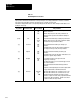
Branch Start This instruction begins a parallel logic path and is entered at
the beginning of each parallel path.
Branch End This instruction ends two or more parallel logic paths and is
used with branch start instructions.
These instructions should not be assigned input image table addresses because input image table words
are reset each I/O scan.
1