
Instruction Manual


Report Generation
Chapter 17
17-12
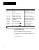
Table 17.F
Address
Delimiters
Delimiter Format Explanation Message Report Format
*XXX* Enter 3digit word address between delimiters. Displays BCD value at assigned word address.
*XXX1*
or
*XXX0*
Enter 3digit word address and a 1" for upper byte or
a 0" for lower byte between delimiters.
Displays the octal value at assigned
byte address.
*XXXXX* Enter 5digit bit address between delimiters. Displays the ON or OFF status of the assigned
bit address.
#XXX# Enter 3,4 or 5digit word address between delimiters. Displays the BCD value at assigned
word address.
!XXX! Enter 3, 4, or 5digit word address between delimiters. Displays the 4digit hex value at address.
&XXX1&
&XXX0&
Enter 3, 4, or 5 digit word address and a 1"for upper
byte or a 0" for lower byte between delimiters.
Displays the octal value at the assigned
byte address.
XXXXX Enter 5, 6, or 7digit bit address between delimiters. Displays the ON or OFF status of the assigned
bit address.
The desired delimiter is entered before and after the bit, byte, or word
address. The delimiter is used to tell the industrial terminal to print the
current status or value of the bit, byte, or word at the address. You can
enter as many consecutive addresses as needed by sharing the same
delimiter, such as *XXX*XXX*XXX*. The asterisk delimiters are used if
the data table size is less than 512 words (not exceeding address 777).
As an example, to report the on/off condition of a device SR6, during each
cycle of machine operation. Delimiters are used to denote the output
address 013/05, and the cycle counter accumulative value (stored at 030).
The desired message, SR6 is (on or off) in cycle (xxx), is entered into
memory with the following keystrokes:
SR6 [space]IS[space]*01305*[space]IN[space]CYCLE[space]#030#[ESC]
Terminate the message entry with the escape [ESC]key. Until [ESC] is
pressed, all key strokes become part of the message. Pressing [ESC]again
returns to the display to the ladder diagram. Pressing [CANCEL
COMMAND] on the PLC-2 family keytop overlay also terminates
message store, and the display returns to the ladder diagram if a peripheral
device was used to enter report generation mode.