
Instruction Manual


Block Transfer
Chapter 14
14-4
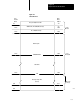
Table 14.A
Timer/Counter
T
ransfer Analogy
Address of Accumulated Value Data Address of Instruction
Accumulated Value in BCD Module Address in BCD (R,G,S)
Address of Preset Value 10
08
Above Data Address
Preset Value in BCD File Address in BCD
After locating the file address in the timer/counter area of the data table,
the processor then duplicates and transfers the file data consecutively one
word at a time until complete, starting at the selected file address.
At the completion of the transfer, a done bit for the read or write operation
is set in the input image table byte as a signal that a valid transfer
has completed.
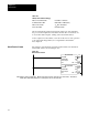
The format of a block transfer read and a block transfer write instruction
with default values is shown in Figure 14.3.
Figure 14.3
Block
T
ransfer Format
EN
Block Xfer Read
Data Addr:
Module Addr:
Block Length:
File:
030
100
01
110
DN
010
07
110
07
110
EN
Block Xfer Write
Data Addr:
Module Addr:
Block Length:
File:
030
100
01
110
DN
010
06
110
06
110
Note: Numbers shown are default values. Numbers in shaded areas must be replaced by userentered values. The number of
default address digits initially displayed (3 or 4) will depend on the size of the data table.
Block Transfer Format