
Instruction Manual


Block Transfer
Chapter 14
14-2
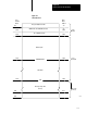
Figure 14.1
Image
T
able Byte Relationship vs Module Position
Data Table
Bit Numbers
10 0717 00
Output Image Table
Control Byte
Input Image Table
Status Byte
010
012
017
110
112
117
Output Image
Table Word,
Lower Byte
Input Image
Table Word,
Lower Byte
Block
Transfer
Module
Left Slot Right Slot
The lower byte of the I/O image table words is used when the module is in the left slot
and the upper byte when the module is in the right slot.
10222
The block transfer read or write operation (Figure 14.2) is initiated in the
program scan and completed in the I/O scan as follows: