Allen Bradley 1772 Mini PLC 2/05 Processor (Cat. No.
Important User Information Because of the variety of uses for this product and because of the differences between solid state products and electromechanical products, those responsible for applying and using this product must satisfy themselves as to the acceptability of each application and use of this product. For more information, refer to publication SGI-1.1 (Safety Guidelines For The Application, Installation and Maintenance of Solid State Control).
Summary of Changes Summary of Changes Summary of Changes This release of the publication contains updated information: For this updated information: See: revised conventions chapter 1 clarification to switch settings for 1772 LSP chapter 3 description of keys on keytop overlay (1770 KCB) chapter 3 corrections to the discussion about automatic restart chapter 18 corrections to the discussion about program control chapter 18 addition of ZCL to glossary appendix B new format all chapters and
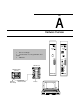
Part Hardware Overview P RUN R O C FAULT MEMORY STORE 1 Before You Begin 2 An Introduction to Programmable Controllers 3 Hardware ON ON P/S ACTIVE MEMORY STORE INTFC INTFC OFF I.
Part Memory / Instruction Set 4 5 6 7 8 9 10 11 12 13 14 15 Memory Organization Scan Theory Relay-type Instructions Program Control Instructions Timers and Counters Data Manipulation Instructions Math Instructions Data Transfer File Instructions Sequencers Jump Instructions and Subroutines Block Transfer Selectable Timed Interrupt Data Table Main Program User Program Subroutine Message Storage Area 110 110 110 010 00 110 10 110 11 00 12 11 110 13
Part Program Editing 16 Program Editing ( ) ( P ) FOR USE WITH PLC 2 FAMILY 1982 ALLEN BRADLEY 975343 02 CAT. NO.
Part Report Generation / Application Programming Techniques 17 18 Report Generation Programming Techniques MS.
Part Program Troubleshooting 19 Program Troubleshooting hr.mn.sec. OFF or ON 00:00'00.00 ON 00:00:00.00 OFF 00:00:00.00 ON 00:00:00.00 On Time On Time Off Time WORD ADDRESS: 0030 BIT NO.
Part Appendices A Number Systems B Glossary C Quick Reference Index Key Sequences: [SEARCH] [Instruction key] (Address) 3 x 82 = 192 5 x 81 = 40 7 x 80 = 7 [SEARCH] [5][3] [Address] [↑]or[↓] 3 5 7 192 40 7 23910 23910 = 3578 8 [SEARCH] [5][3] [←] or [→] [1] or [0] This appendix contains defines terms and abbreviations that because of their complexity or recent introduction are not widely understood.
Table of Contents Summary of Changes . . . . . . . . . . . . . . . . . . . . . . . . . . . . i Before You Begin . . . . . . . . . . . . . . . . . . . . . . . . . . . . . . . . 1 1 An Introduction to Programmable Controllers . . . . . . . . . . 2 1 Hardware . . . . . . . . . . . . . . . . . . . . . . . . . . . . . . . . . . . . . . 3 1 Memory Organization . . . . . . . . . . . . . . . . . . . . . . . . . . . . 4 1 Scan Theory . . . . . . . . . . . . . . . . . . . . . . . . . . . . . . . . . . .
ii Table of Contents Block Transfer . . . . . . . . . . . . . . . . . . . . . . . . . . . . . . . . . . 14 1 Selectable Timed Interrupt . . . . . . . . . . . . . . . . . . . . . . . . . 15 1 Program Editing . . . . . . . . . . . . . . . . . . . . . . . . . . . . . . . . . 16 1 Rules for Editing Instructions . . . . . . . . . . . . . . . . . . . . . . . . . . . . 16 1 Report Generation . . . . . . . . . . . . . . . . . . . . . . . . . . . . . . . 17 1 Programming Techniques . . . . . . . . . . .
1 Chapter Before You Begin Important: Read this chapter before you use the Mini-PLC-2/05 Processor (cat. no. 1772-LS,-LSP). It tells you how to use this manual. Purpose The Mini-PLC-2/05 processor is functionally similar to the Mini-PLC-2/15 processor. The Mini-PLC-2/05 processor has some additional features: selectable timed interrupt memory protect switch fast I/O scan user selectable PROM/RAM backup 3K memory expanded mathematics However, this processor does not have a mode select switch.
Chapter 1 Before You Begin Vocabulary To make this manual easier to read and understand, we refer to the: We Refer to the: As the: Mini PLC 2/05 Processor processor Electrically Erasable Programmable Read Only Memory EEPROM Execute Auxiliary Function EAF Complementary Metal Oxide Semi conductor Random Access Memory CMOS RAM Industrial Terminal (cat. no. 1770 T3) 1770 T3 terminal A glossary at the back of this manual clarifies technical terms.
Chapter 1 Before You Begin Keystroke directions are divided into two columns: tells you what key or keys to press tells you the processor’s action. Related Publications The publication index, publication SD 499, lists all available publications to further inform you about products related to the Mini-PLC-2/05 processor. Consult your local Allen-Bradley distributor or sales engineer for information regarding this publication or any needed information.
Chapter 2 An Introduction to Programmable Controllers Chapter Objectives In this chapter, you review general fundamentals common to our programmable controllers. This chapter: describes what a programmable controller does describe the four major sections of a programmable controller describes how the four major sections of a programmable controller interact gives an example of a simple program Traditional Controls You are probably familiar with the traditional methods of machine control.
Chapter 2 An Introduction to Programmable Controllers Programmable Controls Programmable controllers can perform many of the functions of traditional controls. Sensing devices report to the processors. The output devices at the machine operate the same as they would with traditional controls.
Chapter 2 An Introduction to Programmable Controllers Power Supply Processor (Decision Making) Information Action Input Output • Limit, Proximity, Pressure, • • • • • • • Temperature Switches • • • • Push Buttons Logic BCD Analog Solenoids Motor Starters Indicators Alarms Logic BCD Analog Processor The first section of a programmable controller is the processor. The processor might be called the “brains” of the programmable controller.
Chapter 2 An Introduction to Programmable Controllers Memory Memory serves three functions: stores information in the data table that the CPU may need stores sets of instructions called a program stores messages Data Table The area of memory where data is controlled and used, is called the data table. The data table is divided into several smaller sections according to the type of information to be remembered.
Chapter 2 An Introduction to Programmable Controllers Picture memory as a page that has been divided into many blocks. Each block represents one bit. Since each bit is either on or off, we could show the state of each bit by writing “on” or “off” in each block. However, there is an easier way. We can agree that the numeral one (1) means on and that the numeral zero (0) means off. We can show the status of each bit by writing 1 or 0 into the appropriate block.
Chapter 2 An Introduction to Programmable Controllers For example, you may want this action to take place: ”Whenever a certain limit switch closes.” So your condition could be: “If limit switch number two is closed,...” The action would be: “energize motor starter number one.” The entire statement is then: “If limit switch number two is closed, then energize motor starter number one.” Therefore, when limit switch number two at the machine closes, the programmable controller energizes the motor starter.
Chapter 2 An Introduction to Programmable Controllers You should also notice another important characteristic of input indicators. They are only associated with terminals used for wiring sensing devices to the input section. The terminal that’s used to provide a ground for the sensing circuits has no indicator. Conditioning Another function of the input is signal conditioning. The electrical power used at the machine is usually not compatible with the signal power used within the programmable controller.
Chapter 2 An Introduction to Programmable Controllers Isolation The output isolates the more sensitive electronic circuitry of the programmable controller from unwanted and dangerous voltages that occasionally occur at the machine or the plant’s wiring system. Some situations require additional external protection. Power Supply The fourth section is the power supply. It provides a low level dc voltage source for the electronic circuitry of the processor.
Chapter 2 An Introduction to Programmable Controllers Important: Figure 2.1 is for demonstration purposes only. We do not show the associated wiring, a motor starter, or an emergency stop button. Since the limit switch is wired normally-closed, the conveyor motor will run until the arriving part opens the switch. At that time, the condition for energizing the motor is not longer met. Therefore, the motor is de-energized. When the condition is met, we say it is true.
Chapter 2 An Introduction to Programmable Controllers Figure 2.2 Scan Sequence Output Image Table Output Terminals Copy output image table status into output terminal circuits. I/O Scan Input Image Table Input Terminals Copy input terminal status into input image table. Program Statement Program Scan Execute each program rung in sequence, writing into bits in the data table, including the output image table.
Chapter 2 An Introduction to Programmable Controllers Next, the processor scans the program. It does this statement by statement. Each statement is scanned in this way: 1. For each condition, the processor checks, or “reads,” the image table to see if the condition has been met. 2. If the set of conditions has been met, the CPU writes a one into the bit location in the output image table corresponding to the output terminal to be energized.
Chapter 2 An Introduction to Programmable Controllers The processor scans the program. Our program states that if (conditions) input bit 02 is on, turn on output 02. If input bit 02 is off then output bit 02 is off. Since the alter condition is not true, the processor turns off output bit 02. When the processor next scans the output image table, it sees the zero in output bit 02 and responds by de-energizing output terminal 02. The action causes the conveyor to stop.
Chapter 3 Hardware Chapter Objectives This chapter is a summary of the Mini-PLC-2/05 Processor Assembly and Installation Manual, publication 1772-6.6.6. In this chapter, you will read about: major features general features hardware features optional features Major Features A complete processor system consists of the following major components: Mini-PLC-2/05 processor I/O chassis power supply I/O modules (up to 16 modules) industrial terminal (cat. no.
Chapter 3 Hardware Hardware Features Mini PLC 2/05 Processor (cat. no. 1772 LS) The Mini-PLC-2/05 Processor (cat. no. 1772-LS) comes equipped with the following hardware features (Figure 3.1): Figure 3.1 Mini PLC 2/05 Processor (cat. no.
Chapter 3 Hardware Processor Status Indicator PROC RUN/FAULT: This red/green LED keeps you informed of the processor’s operating conditions. Table 3.A Status Indication Status Indicator If the color is Then the Indication represents PROC RUN/FAULT Green The processor module is in the run mode and will begin operation. The EEPROM memory module (if present) is being programmed. There is a fault. Recycle power to reset the processor module.
Chapter 3 Hardware Mini PLC 2/05 Processor (cat. no. 1772 LSP) The Mini-PLC-2/05 Processor (cat. no. 1772-LSP) contains all the hardware features of the LS processor and in addition contains the following (Figure 3.2): Figure 3.2 Mini PLC 2/05 Processor with Power Supply (cat. no. 1772 LSP) P RUN R P/S O C FAULT ACTIVE ON MEMORY STORE ON P/S PARALLEL A B INTFC POWER ON OFF I.
Chapter 3 Hardware Fuse Purpose: Guards against overcurrent conditions on the input line. Sizes: 1.0 amp fuse for 120V AC operations Terminal Strip Purpose: To provide wire connections for the processor. Hardware: Terminals L1, N and GND label the AC input connections. Switch Assembly on the I/O Chassis Purpose: Determines processor response to memory protect and power-up sequence. Location: Left side of the I/O chassis backplane. Settings: If Then Switch 8 is on Memory protection is on.
Chapter 3 Hardware Battery Backup Purpose: Provides battery backup power for the processor’s memory. Hardware: Size AA, 3.6V Lithium Battery, 1.785 amp hr, 0 to 70oC Function: In order for you to retain processor memory after loss of power, the processor contains an AA size lithium battery. A removeable holder located at the rear of the processor module houses your battery. This battery supports stored memory for up to two years. We recommend documenting the start-up date of your processor.
Chapter 3 Hardware Installation Before you start to program your processor make sure all of your peripheral equipment is installed properly. Follow these basic instructions to install the industrial terminal to the processor. Refer to Figure 3.4 when following these instructions. Figure 3.4 Industrial Terminal Installation Mini PLC 2/05 Industrial Terminal (rear view) Channel A PLC 2 Family Program Panel Interconnect Cable Interface 10249 1.
Chapter 3 Hardware 4. Place the PLC-2 Family Keytop Overlay (cat. no. 1770-KCB) (Figure 3.5) onto the keyboard. Figure 3.5 PLC 2 Family Keytop Overlay MODE SELECT DATA INIT RECORD EXPAND ADDR RUNG DISPLAY HELP SBR (RET) LBL EAF T.
Chapter 3 Hardware second row of keys RECORD enter new data specify rung RUNG enter 3 digit divide ( enter get [ G ] ) enter up counter (CTU) C SHIFT – enter C 9 enter 9 specify search enter immediate input [ I ] enter timer on delay (TON) enter branch end SEARCH enter output latch ( L ) A SHIFT – enter A B SHIFT – enter B 7 enter 7 8 enter 8 third row of keys display specified data DISPLAY INSERT enter 3 digit multiply ( X ) insert the next specified item enter eq
Chapter 3 Hardware fifth row of keys SHIFT access function on top half of keys that support two functions SHIFT – move cursor right move cursor right CANCEL COMMAND SHIFT – move cursor leftcursor left move enter 3 digit add enter put ( + ) enter immediate output (IOT) end current function without saving (ZCL) enter output energize (PUT) enter zone control last state enter retentive timer reset (RTR) enter examine on FORCE ON ( ) enter a 0 0 FORCE OFF specify force off speci
Chapter 3 Hardware Run/Program Remote test Remote Program [SEARCH] 590 [SEARCH] 591 [SEARCH] 592 ATTENTION: Use only Allen-Bradley authorized programming devices to program Allen-Bradley programmable controllers. Using unauthorized programming devices may result in unexpected operation, possibly causing equipment damage and/or injury to personnel. Important: When power is re-applied following a power failure and if switch 6 is on, the processor returns to the last programmed mode of operation.
Chapter 3 Hardware To display: Press individually: 1011 1011 Some keys have two symbols occupying one key (Figure 3.5). To display the top section of each key use your shift key before the desired symbol. For example: Press 7: Press[SHIFT] A: To display 7 To display A Data Monitor Functions - You can display on a CRT and print directly to a data terminal - binary, hexadecimal, and ASCII data monitor functions by performing the keystrokes in table 16.B.
Chapter 4 Memory Organization Chapter Objectives In this chapter, you will read about: hardware and its relationship to your program memory and its components This chapter provides detailed concepts of the memory’s organization and its structure. Understanding these concepts aids you in programming your processor.
Chapter 4 Memory Organization Figure 4.1 Word Address Equals Memory Bits Concept Example Hardware Terminology Hardware Terminology Input (1) or Output (0) Output: 0 Rack No. (Always 1) Rack No.: 1 Module Group No. (0-7) Module Group No.: 0 Terminal No. (00-07, 10-17) Terminal No.
Chapter 4 Memory Organization Memory Areas Memory is divided into three major sections: data table, user program and a message storage area. The areas store input status, output status, your program instructions and messages. We describe these areas in detail so you can gain programming flexibility using your processor. Data Table The first part of memory is the data table (Figure 4.2). The processors are factory configured for 128 words. Figure 4.
Chapter 4 Memory Organization Figure 4.3 Data Table Organization, Factory Configured Total Decimal Words 8 8 Bit Address Word Address Decimal Words Per Area Processor Work Area No. 1 000 00 007 010 17 00 017 020 17 00 026 027 030 17 077 100 17 00 107 110 17 00 117 120 17 00 Output Image Table 16 8 Bit/Word Storage 24 64 72 8 40 8 Reserved 1 2 Timer/Counter Accumulated Values (AC) (or Bit/Word Storage) Processor Work Area No.
Chapter 4 Memory Organization The data table area is a major part of memory. It is divided into six sections which includes the input and output image tables. (These two areas were described in chapter 2). The processor controls and utilizes words stored in the data table. The input devices coupled with the control logic from your program determines the status of the output devices. Input devices are limit switches, pushbutton switches, pressure switches, etc.
Chapter 4 Memory Organization To expand your data table do this: SEARCH The word SEARCH appears in the lower left hand corner of the screen. 50 DATA TABLE CONFIGURATION NUMBER OF 128 WORD D.T.
Chapter 4 Memory Organization Data Table Areas The following areas make up the data table. They are: processor work area no. 1 output image table bit/word storage (020-027) timer/counter accumulated values and internal storage processor work area no. 2 input image table bit/word storage (120-127) timer/counter preset values and internal storage Chapter 1 describes the input and output image tables. The following sections describe the remaining areas.
Chapter 4 Memory Organization User Program The second major part of memory is the user program (Figure 4.2). It is divided into two areas: main ladder diagram program subroutine area The user program area begins at the end of the data table. Main Program Purpose: The program is a group of ladder diagram and functional block instruction used to control an application. Description: A program is a list of instructions that guides the processor.
Chapter 4 Memory Organization Message Storage Area The third major part of memory is the message storage area (Figure 4.2). You can print out messages in hard copy form. You can store up to 70 messages using the 1770-T3 industrial terminal, or 198 messages using the 1770- T3 terminal with the 1770-RG module. Message storage follows the end statement of your program and is limited by the number of unused words remaining in memory. Each word stores two message characters.
Chapter 5 Scan Theory Chapter Objectives In this chapter you will read about: scan function scan time Scan Function The processor controls the status of output devices or instructions in accordance with program logic. Every instruction in your program requires execution time. These times vary greatly depending upon the instruction, the amount of data to be operated on, and whether the instruction is true or false. As a review from chapter 1, there are two types of scans (Figure 5.
Chapter 5 Scan Theory Figure 5.1 Scan Sequence Output Image Table Output Terminals Copy output image table status into output terminal circuits. I/O Scan Input Image Table Input Terminals Copy input terminal status into input image table Program Statement Program Scan Execute each program rung in sequence, writing into bits in the data table, including the output image table.
Chapter 5 Scan Theory On power-up, the processor begins the scan sequence with the I/O scan. Data from output image table is written to the output modules. Data from the input modules is read into the input image table. Next, the processor scans the program statement by statement: 1. For each condition, the processor checks, or “reads,” the image table to see if the condition has been met. 2.
Chapter 5 Scan Theory Add the execution values for each instruction by using Table 5.A. The sum of these values added to the I/O scan time is the average scan time. Table 5.
Chapter 5 Scan Theory Instruction Name Symbol Instruction True Instruction False Label Return Jump to subroutine Jump Block transfer read LBL (RET) (JSR) (JMP) BLOCK X FER 1 34 30 100 55 80 15 15 15 75 Block transfer write BLOCK X FER 0 80 75 Sequencer load SEQ 2 390(80/extra word) 105 Sequencer input SEQ 1 420(90/extra word) 55 Sequencer output SEQ 0 470(90/extra word) 110 File to word move Word to file move File to file move FILE 12 FILE 11 FILE 10440 (+10/word transferre
Chapter 6 Relay type Instructions Chapter Objectives This chapter describes: relay-type instructions how to define conditions before an action takes place Programming Logic A program is a list of instructions that the processor executes. These instructions can examine or change the status of bits in the data table of the processor. The status of these bits can determine the operation of other instructions.
Chapter 6 Relay-type Instructions C1 = Input switch 1. When the switch is on, this condition is true. This switch turns on a conveyer belt. C2 = Input sensor 1. When the sensor is off, this condition is true. This sensor detects if the temperature in the factory is below 40oC. C3 = Input sensor 2. When the sensor is on, this condition is true. This sensor detects the presence of a part of the conveyer belt. A = The part will be drilled.
Chapter 6 Relay-type Instructions Each input and output bit has a five-digit address. Reading from left to right: the first number denotes the type of I/O module: - 0 output - 1 input the second number denotes an I/O chassis and it always is a 1. the third number denotes a module group. This number will range from 0-7.
Chapter 6 Relay-type Instructions Keystrokes: Enter an Examine On or Examine Off instruction by performing the following steps. 1. Press either -] [- or -]/[- as required. 2. Enter
. Removing the Examine On or Examine Off Instruction You remove an Examine On or a Examine Off instruction by performing the following steps. 1. Position the cursor over the Examine On or Examine Off instruction you want to remove. 2. Press [REMOVE] -] [- or -]/[-.Chapter 6 Relay-type Instructions Keystrokes: You enter an Output Energize instruction by performing the following steps. 1. Press -( )-. 2. Enter
. Removing an Output Energize Instruction The only way you remove an Output Energize instructions is to remove the entire rung. See chapter 16. Editing in a Completed Rung You edit the Output Energize instruction by performing the following steps. However, you cannot remove an output instruction. 1.Chapter 6 Relay-type Instructions These instructions control a specific bit based on the rung condition. When its rung conditions are: True - Output Latch sets a specified bit. True - Output Unlatch resets a specified bit. False - No action is taken. Keystrokes: You enter an Output Latch or Unlatch instruction by performing the following steps. 1. Press either -(L)- or -(U)- as required. 2. Enter
.Chapter 6 Relay-type Instructions Here two conditions are parallel. As long as one of the conditions (C1 or C2) is true, a continuous path to the action exists. Therefore, the action is performed. True False C1 C2 True True C3 C4 A Here are two sets of parallel conditions. If either set of conditions are true, the action is performed. 010 110 010 00 110 10 00 12 This illustration shows a program rung with branching, as it would appear by the 1770-T3 terminal display.
Chapter 6 Relay-type Instructions Removing a Branch Start or Branch End Instruction You remove either a Branch Start or Branch End instruction or change an instruction type by performing the following steps. 1. Position the cursor over either the Branch Start or Branch End instruction. 2. Press [REMOVE] [ ] or [ ]. Inserting a Branch Instruction in a Completed Rung You insert either a Branch Start or Branch End instruction or change an instruction type by performing the following steps. 1.
Chapter 6 Relay-type Instructions Creating nested branches is not possible because the branch end instruction completes a branch group. But the above rung shows a single branch group with two branch end instruction. Above, the examine on instruction with the address 11012 is actually a branch group within a branch group.
Chapter 7 Program Control Instructions Chapter Objectives This chapter describes these program control instructions: output override immediate I/O update Introduction Some applications need programming techniques designed to override a group of non-retentive outputs or update I/O ahead of the usual I/O scan time. The program control instructions satisfy this need.
Chapter 7 Program Control Instructions To override a group of output devices, you must use two MCR (Figure 7.1) or ZCL (Figure 7.2) instructions: one each to begin the zone and one each to end the zone. The start fence is always programmed with a set of input conditions. The end fence must be programmed unconditionally. Figure 7.
Chapter 7 Program Control Instructions If the start fence becomes: True - Each rung condition controls their output instruction. False - All output instructions within the zone are left in their last state. The same outputs may now be controlled by another zone program. Only one zone may control a set outputs at one time. Keystrokes: You enter an MCR or ZCL instruction by performing the following steps. 1. Press either -(MCR)- or -(ZCL)-.
Chapter 7 Program Control Instructions Figure 7.3 Immediate Input Instruction I/O Scan Program Scan Immediate Input Instruction Interrupts Program Scan 2 Examine Bits in Word 112 Here in Program Returns to Program Scan Word 112 16 Bits from One Module Group Written into Input Image Table Word Module Group (Input) 10151 I An Immediate Output Update instruction interrupts the program scan to update the module group with data from corresponding output image table word address (Figure 7.4).
Chapter 7 Program Control Instructions Figure 7.4 Immediate Output Instruction I/O Scan Program Scan Control Bits of Word 014 Here in Program Immediate Output Instruction Interrupts Program Scan Returns to Program Scan Word 0 4 Writes All 16 Bits from One Output Image Table Word to One Module Group Module Group (Output) 10152 I Important: These instructions significantly impact program scan time. Use them only when absolutely necessary.
Chapter 7 Program Control Instructions Removing an Immediate Output Update Instruction The only way to remove an Immediate Output Update instruction is to remove the entire rung. See chapter 11. Removing an Immediate Input Update Instruction You remove an Immediate Input Update instruction by performing the following steps. 1. Position the cursor over the Immediate Input Update instruction you want to remove. 2. Press [REMOVE]-[I]-.
Chapter 8 Timers and Counters Chapter Objectives This chapter describes two instructions that keep track of timed intervals or counted events: timers counters Introduction Timer and counter instructions are output instructions internal to the processor. They provide many of the capabilities available with timing relays and solid state timing/counting devices.
Chapter 8 Timers and Counters Two bits in the accumulated value word are status bits: Bit 15 is the timed bit. It is either set or reset when the timer has timed out. The setting or resetting depends on the type of timer instruction used. Bit 17 is the enable bit. It is set when rung conditions are true and is reset when rung conditions are false.
Chapter 8 Timers and Counters Timer Off Delay The Timer Off Delay instruction is programmed as an output instruction. 010 00 030 TOF 1.0 PR 150 AC 000 When the timer off delay rung condition becomes: True Bit 15 is set. Bit 17 is set. Accumulated value resets to 000. False Timer cycle begins. Timer increments its AC value. Bit 15 resets when the AC=PR and the timer stops timing. Bit 17 is reset. Keystrokes: You enter a Timer On or a Timer Off Delay instruction by performing the following steps. 1.
Chapter 8 Timers and Counters Retentive Timer On/Reset Retentive Timer On Purpose: The Retentive Timer On accumulates the amount of time that the preconditions of its rung are true. It controls one or more outputs (by means of other rungs) after the total accumulated time is equal to the preset time. Whenever the rung is false, the accumulated time is retained. If the outputs have been energized, they remain on. The accumulated time and energized outputs are retained if power is removed from the processor.
Chapter 8 Timers and Counters When the rung condition becomes: True RTR instruction resets the accumulated value of the RTO instruction. Bits 15 and 17 are reset. False No action is taken. Keystrokes: You enter a Retentive Timer On or a Retentive Timer Reset instruction by performing the following steps. 1. Press -(RTO)- or -(RTR)-. 2. Enter
. Perform the following step for a Retentive Timer instruction only. 3. Enter Chapter 8 Timers and Counters The upper four bits in the accumulated value (AC) word are status bits: Bit 14 - Overflow/underflow bit. It is set when the AC value of the CTU instruction exceeds 999 or when the AC value of the CTD instruction falls below 000. Bit 15 - Count complete bit. it is set when the AC value > PR value. Bit 16 - Enable bit for CTD instruction. It is set when the rung condition is true. Bit 17 - Enable bit for CTU instruction. It is set when the rung condition is true.
Chapter 8 Timers and Counters The Up Counter instruction retains its AC value when: You change the mode to the remote program. The rung condition turns false. A power outage occurs and memory backup is maintained. Important: Bit 14 of the accumulated value word is set when the accumulated value either overflows or underflows. when a down counter preset is 000, the underflow bit 14 will not be set when the count goes below 0.
Chapter 8 Timers and Counters When the rung condition becomes: True Accumulated value of the specified counter is reset to 000. Status bits (14,15,16,17) are reset. False No action is taken. Keystrokes: You enter an Up Counter, Down Counter or Counter Reset instruction by performing the following steps. 1. Press -(CTU)-, -(CTD)-, or -(CTR)-. 2. Enter
. Important: Do not perform steps 3 and 4 for a Counter Reset instruction. 3. Enter . 4. Enter .Chapter 9 Data Manipulation Instructions Chapter Objectives In this chapter, you will read about two types of instructions used to transfer and compare data and how to use these instructions to perform operations of data that is stored in the data table. These types of instructions are: transfer instructions compare instructions Transfer Instructions There are two data transfer instructions. They are: get put Get Purpose: A Get instruction accesses all 16 bits of one word location in the data table.
Chapter 9 Data Manipulation Instructions Put Purpose: A Put instruction receives all 16 bits of data from the immediately preceding Get instruction and stores the data at the specified data table word location. Use with a Get instruction to form a data transfer rung. Programmed in the output side of the ladder diagram rung. This instruction can have the same address as other instructions in the program. It must be immediately preceded by a Get or a Get-Byte instruction.
Chapter 9 Data Manipulation Instructions Editing a Get Instruction in a Partially Completed Rung 1. Enter the next instruction. 2. Position the cursor over the Get instruction you want to change. 3. Press -[G]- or any other appropriate instruction type key. 4. Enter
. 5. Enter if appropriate. Editing a Get or Put Instruction in a Completed Rung 1. Position the cursor over the Get or Put instruction you want to change. 2.Chapter 9 Data Manipulation Instructions Keystrokes: You enter an Equal To instruction by performing the following steps. 1. Press -[=]-. 2. Enter
. 3. Enter if appropriate. Removing an Equal To Instruction You remove an Equal To instruction by performing the following steps. 1. Position the cursor over the Equal To instruction you are going to remove. 2. Press [REMOVE] -[=]-. Editing a Completed Rung You edit an Equal To instruction by performing the following steps.Chapter 9 Data Manipulation Instructions Keystrokes: You enter a Less Than instruction during initial programming by performing the following steps. 1. Press -[<]-. 2. Enter
. 3. Enter . Removing the Less Than Instruction You remove a Less Than instruction by performing the following steps. 1. Position the cursor over the Les Than instruction you want to remove. 2. Press [REMOVE] -[<]-.Chapter 9 Data Manipulation Instructions There are two cases for comparison: Case 1. Lower Limit YYY Upper Limit 010 120 0451 050 200 B L 170 06 YYY8 05 If YYY is equal to or greater than 170 and equal to or less than 200, the comparison is true and logic continuity is established. If YYY is less than 170 or greater than 200, the comparison is false and logic continuity is not established. 3778 False 2008 YYY8 True 1708 False 000 Case 2.
Chapter 9 Data Manipulation Instructions If YYY is equal to or less than 200 and equal to or greater than 170, the comparison is false and logic continuity is not established. If YYY8 is greater than 200 or less than 170, the comparison is true and logic continuity is established. Keystrokes: You enter a Limit Test instruction by performing the following steps. 1. Press -[L]-. 2. Enter
. 3. Enter . 4. Enter .Chapter 9 Data Manipulation Instructions 120 030 037 G < 04 YYY 237 037 = 237 010 02 When YYY 237, GET/LES EQU comparison is true and 010/03 is energized. Important: Only one Get instruction is required for a parallel comparison. The Les and Equ instructions are programmed in parallel branches. Keystrokes: You enter an equal to or less than comparison by following the following steps. 1. Press -[G]-. 2. Enter
. 3. Enter . 4. Press [ ] 5. Press -[<]-. 6.Chapter 9 Data Manipulation Instructions Greater Than Purpose: A greater than comparison is also made with the Get/Les pair of instructions. This time the Get instruction BCD value is the reference and the Les instruction BCD value is the changing value. The Les value is compared with to the Get value for a greater than condition. When the Les value is greater than the Get value, the comparison is true and logic continuity is established.
Chapter 9 Data Manipulation Instructions Keystrokes: You enter an Equal To or Greater Than comparison by performing the following steps. 1. Press -[G]-. 2. Enter
. 3. Enter . 4. Press [ ]. 5. Press -[=]-. 6. Enter . 7. Enter . 8. Press [ ]. 9. Press -[<]-. 10. Enter . 11. Enter . 12. Press [ ]. 13. Press -( )-. 14. Enter . Editing the Operation See the editing Get, Les, Equ and branching instructions.Chapter 9 Data Manipulation Instructions Keystrokes: You enter a Get Byte instruction by performing the following steps. 1. Press -[B]-. 2. Enter
. 3. Enter . Editing the Operation You edit the Get Byte comparison by performing the following steps. 1. Position the cursor over -[B]-. 2. Press -[B]-. 3. Enter . 4. Enter .Chapter 9 Data Manipulation Instructions Case 2. Two Get Bytes XXXD XXXD B B WWW8 YYY8 XXX WWW YYY D word address octal values upper or lower byte 040 PUT BCC BBCCC 16 only these three letters are displayed 0 lower byte 1 upper byte Two Get Byte instructions are programmed in the condition area of the ladder rung. It tells the processor to make a duplicate of all 8 bits in each addressed byte.
Chapter 9 Data Manipulation Instructions Editing the Operation You edit a Get Byte/Put instruction by performing the following steps. 6. Position the cursor over -[B]-. 7. Press -[B]-. 8. Enter
. 9. Enter . Important: Repeat steps 2, 3 and 4 when using two Get Byte instructions. 10. Press -(PUT)-. 11. Enter . Chapter Summary We showed you how to transfer and compare data. Also, we showed you how to use these instructions to perform comparison operations.Chapter 10 Math Instructions Chapter Objectives This chapter describes two different types of math operations: three digit math expanded math Table 10.A lists definitions of some mathematical terms. Table 10.
Chapter 10 Math Instructions Addition, Subtraction, Multiplication and Division Addition Reports the sum of two values from the two Get instructions immediately preceding the addition instruction. Programmed in the output position of the ladder diagram rung. The sum is stored in the add instruction word address. 030 G 320 031 G 380 032 + 700 When the sum exceeds 999, the overflow bit (bit 14) in the add instruction word is set.
Chapter 10 Math Instructions Multiplication Reports the product of two values stored in the Get instruction words immediately preceding the multiply instruction. Programmed in the output position of the ladder diagram. The product is stored in two multiplication instruction words. The first word contains the most significant digit and the second word contains the least significant digit. If the product is less than six digits, leading zeros appear in the product.
Chapter 10 Math Instructions 6. Enter if appropriate. 7. Close the rung by pressing the appropriate math instruction key (Table 10.B). Table 10.B Three Digit Math Functions 8. Addition ( + ) Subtraction ( ) Multiplication ( x ) Division ( ÷ ) Enter . Editing a Completed Rung You edit a three digit math operation to change an address or the instruction type by performing the following steps. Expanded Math 1.
Chapter 10 Math Instructions Figure 10.
Chapter 10 Math Instructions Figure 10.2 Data Address Format Operand A is stored in the data table like this: 17 16 15 14 13 10 7 4 3 0 X S X X M L K Integer High Word X X X X J H G Integer Low Word X X X X F E D Decimal High Word X X X X C B A Decimal Low Word Operand A is displayed in the 1770 T3 industrial terminal like this: M L K J H G F E D C B A • implied and not displayed.
Chapter 10 Math Instructions Conditioning Instructions The conditioning instructions (operand B) may require up to four data table words (Figure 10.2). We use Get instructions to enter data for operand B that can contain an: addend subtrahend multiplier divisor root conversion word Operand B has the format xxx xxx.xxx xxx. Enter it from the keyboard of the 1770-T3 industrial terminal or through ladder diagram instructions. The number you enter has a fixed decimal point.
Chapter 10 Math Instructions Figure 10.
Chapter 10 Math Instructions bit 14 - overflow/underflow/illegal bit; significance depends on the arithmetic operation being performed at the time overflow (addition) - set indicates result exceeds displayable result overflow (subtraction) - set indicates result exceeds displayable result overflow or underflow (multiplication) - set indicates result exceeds displayable result illegal (division) - set indicates division by zero or result exceeds result word range In this section, unused status bits are show
Chapter 10 Math Instructions Figure 10.4 Optional Ladder Diagram for EAF Addition Result Operand A Operand B 060 G 000 040 G 000 050 G 000 061 G 000 041 G 000 051 G 000 062 G 000 042 G 000 052 G 000 063 G 000 043 G 000 053 G 000 Start Executive Aux Function Function Number: Data Addr: Result Addr: 01 040 060 In the optional ladder diagram (Figure 10.4), the first branch contains the result (term C). The second branch contains the data address or operand A (term A).
Chapter 10 Math Instructions Expanded Math Operations Your processor executes the following expanded math operations and maintains the proper sign of the result: addition subtraction multiplication division BCD to binary conversion Binary to BCD conversion square root (not a signed function) Addition, Subtraction, Multiplication, and Division Addition Reports the sum (result address) of the augend (operand A, the data address) and the addend (operand B, the conditioning gets).
Chapter 10 Math Instructions Multiplication Reports the product (result address) of a multiplicand (data address) and a multiplier (conditioning gets). Operands can only be six digits. 060 G 000 040 G 000 050 G 000 061 G 000 041 G 000 051 G 000 062 G 000 042 G 000 052 G 000 063 G 000 043 G 000 053 G 000 Start Executive Aux Function Function Number: Data Addr: Result Addr: 03 040 060 Division Reports the quotient (result address) of a dividend (data address) and a divisor (conditioning instructions).
Chapter 10 Math Instructions 9. Enter if appropriate. 10. Press -[G]-. 11. Enter . 12. Enter if appropriate. 13. Close the rung. Press [SHIFT][EAF]. 14. Enter the appropriate function number 15. Enter . 16. Enter . Optional Ladder Diagram Keystrokes: You enter the instructions for an alternate ladder diagram to monitor an addition, subtraction, multiplication, or division operation by performing the following groups of steps.
Chapter 10 Math Instructions 1. Press the branch start key [ ]. 2. Press -[G]-. 3. Enter
. 4. Enter if appropriate. 5. Press -[G]-. 6. Enter . 7. Enter if appropriate. 8. Press -[G]-. 9. Enter . 10. Enter if appropriate. 11. Press -[G]-. 12. Enter . 13. Enter if appropriate. The third group of steps you perform enters the branch for term B. 1. Press the branch start key [ ]. 2. Press -[G]-. 3. Enter . 4.Chapter 10 Math Instructions 13. Enter if appropriate. 14. Close the branches. Press the branch end key [ ]. 15. Complete the rung. Press [SHIFT][EAF]. 16. Enter the appropriate function number (Table 10.C). 17. Enter . 18. Enter . Editing a Completed Rung Operands A, B and Result: Follow the editing procedures for a Get instruction. EAF Instruction: You can edit an EAF instruction to change an address or the function by performing the following steps. 1.
Chapter 10 Math Instructions Figure 10.6 Optional Ladder Diagram for EAF Square Root 060 G 000 050 G 000 061 G 625 051 G 625 062 G 000 052 G 000 063 G 000 053 G 000 Start Executive Aux Function Function Number: Data Addr: Result Addr: 05 010 060 Only the six most significant digits are taken for a square root. The result is displayed in the result address words.
Chapter 10 Math Instructions execute and monitor an square root operation by performing the following steps. The first group of steps you perform enters the branch for the result. 1. Open the rung. Press the branch start key [ ]. 2. Press -[G]-. 3. Enter
. 4. Enter if appropriate. 5. Press -[G]-. 6. Enter . 7. Enter if appropriate. 8. Press -[G]-. 9. Enter . 10. Enter if appropriate. 11. Press -[G]-. 12. Enter . 13.Chapter 10 Math Instructions 10. Enter if appropriate. 11. Press -[G]-. 12. Enter . 13. Enter if appropriate. 14. Close the branches. Press the branch end key [ ]. 15. Close the rung. Press [SHIFT][EAF]. 16. Enter 05 (function number). 17. Enter 010 (data address). 18. Enter . Editing a Completed Rung Operand and Result: Follow the editing procedures for a Get instruction.
Chapter 10 Math Instructions Figure 10.7 Optional ladder diagram for BCD to Binary Conversion 060 G 2DE 050 G 000 Start 051 G 734 Executive Aux Function Function Number: Data Addr: Result Addr: 13 010 060 If the operand is greater than (+) 32 767, the result 7FFFh is displayed. If the operand is more negative than (-) 32 767, the result 8001 is displayed at the result address. All negative values are stored as 2’s complement.
Chapter 10 Math Instructions 10. Enter 13 (function number). 11. Enter 010 (default number). 12. Enter . Editing a Completed Rung Operand and Result: Follow the editing procedures for a Get instruction. EAF Instruction: You can edit a conversion operation to change an address by performing the following steps. 1. Press [SHIFT][EAF]. 2. Enter 13 (function number). 3. Enter 010 (data address). 4. Enter .
Chapter 10 Math Instructions 4. Enter if appropriate. 5. Press -[G]-. 6. Enter . 7. Enter if appropriate. The second group of steps you perform enters the branch for the number to be converted (term F). 1. Open the rung. Press the branch start key [ ]. 2. Press -[G]-. 3. Enter . 4. Enter if appropriate. 5. Close the branches. press the branch end key [ ]. 6. Close the rung. Press [SHIFT][EAF]. 7. Enter 14 (function number). 8.
Chapter 11 Data Transfer File Instructions Chapter Objectives This chapter describes the data transfer file instructions: file to file move word to file move file to word move A file is a group of consecutive data table words used to store information. A file can be between 1 and 999 words in length. The address of word 1 defines the address of the file. When displayed, the words of a file are designated consecutively by positions 001-999 according to the length of the file.
Chapter 11 Data Transfer File Instructions Figure 11.
Chapter 11 Data Transfer File Instructions An internally indexed file instruction has a done bit and an enable bit. The done bit is bit 15 and the enable bit is bit 17. These bits are automatically entered from the counter address. The enable bit is set when the rung logic goes from a false to true transition; the done bit is set when the file instruction is completed. Modes of Operation There are three modes of operation based on the rate per scan.
Chapter 11 Data Transfer File Instructions For each true rung condition, the instruction is enabled. The number of words equal to the rate per scan is operated upon during one scan. The process is repeated over a number of consecutive scans until the entire file has been operated upon. Once the file instruction is enabled it remains enabled for the number of scans necessary to complete the operation.
Chapter 11 Data Transfer File Instructions Data Monitor Display Once you establish your file data, you’ll want to edit, load, or monitor your file data. To do these functions the processor has a data monitor mode. This mode lets you access your file in three ways; either by displaying binary, hexadecimal, or ASCII values (Figure 11.2) Figure 11.
Chapter 11 Data Transfer File Instructions The binary data monitor display lets you manipulate one word at a time by displaying each bit using binary digits. The hexadecimal monitor display lets you manipulate 4 digits which represents word values. The ASCII monitor display converts 4 digits to the ASCII code. The industrial terminal can automatically convert data from one number system to the other when the alternate display is selected.
Chapter 11 Data Transfer File Instructions Use the following illustration as you read about each file instruction. Key Sequence FILE 10 FILE 11 FILE 12 1770-T3 Display Instruction Notes File To File Move Counter Addr: 030 Position: 001 File Length: 001 File A: 110-110 File R: 110-110 Rate Per Scan: 001 030 EN 17 Output instruction. 030 DN 15 Counter is internally incremented by the instruction.
Chapter 11 Data Transfer File Instructions Before You Begin Put the processor in the program mode. You may have to expand your data table to provide additional space for files. To do this: [SEARCH] 50 There is no change in the screen display. DATA TABLE CONFIGURATION NUMBER OF 128-WORD D.T. BLOCKS NUMBER OF INPUT/OUTPUT RACKS NUMBER OF T/C (If applicable) DATA TABLE SIZE 01 2 40 128 The following chart will help you adjust the data table size of your processor.
Chapter 11 Data Transfer File Instructions File to File Move Purpose: Duplicates and transfers the source file to the destination file address you identified. The source file remains intact. Programmed as an output instruction; requires five words of the user program area. The counter is incremented internally by the instruction. ATTENTION: The counter address for the file-to-file move instruction should be reserved for that instruction. Do not manipulate the counter accumulated or preset word.
Chapter 11 Data Transfer File Instructions Insert the following values. The cursor moves automatically through the file instruction. The values are: COUNTER ADDR - 200 POSITION - 001 FILE LENGTH - 007 FILE A - 400 FILE R - 500 RATE PER SCAN - 007 200 File To File Move Counter Addr: 200 Position: 001 File Length: 001 File A: 110-110 File R: 110-110 Rate Per Scan: 001 030 EN 17 030 DN 15 Now the cursor is on the first digit of the file length.
Chapter 11 Data Transfer File Instructions The cursor moved to the first digit of file R. 500 File To File Move Counter Addr: 200 Position: 001 File Length: 007 File A: 400 406 File R: 500 506 Rate Per Scan: 0 07 030 EN 17 030 DN 15 Finally, the cursor is on the first digit of the rate per scan. 007 File To File Move Counter Addr: 200 Position: 001 File Length: 007 File A: 400 406 File R: 500 506 Rate Per Scan: 007 030 EN 17 030 DN 15 You can now proceed to add data to your file.
Chapter 11 Data Transfer File Instructions This example uses the hexadecimal data monitor display. [DISPLAY] The screen does not change 1 Counter Addr: 200 File A: 400 406 POSITION 001 002 003 004 005 006 007 HEXADECIMAL DATA MONITOR FILE TO FILE MOVE POSITION: 001 FILE A DATA 0000 0000 0000 0000 0000 0000 0000 Data: 0000 File Length: 007 File R: 500 506 FILE R DATA 0000 0000 0000 0000 0000 0000 0000 Important: :If you want to enter binary information, press [DISPLAY][0].
Chapter 11 Data Transfer File Instructions 1257 Counter Addr: 200 File A: 400 406 POSITION 001 002 003 004 005 006 007 HEXADECIMAL DATA MONITOR FILE TO FILE MOVE POSITION: 001 FILE A DATA 1257 0000 0000 0000 0000 0000 0000 Data: 1257 File Length: 007 File R: 500 506 FILE R DATA 0000 0000 0000 0000 0000 0000 0000 This information (1257) now appears in position 001 of file A. The command buffer at the bottom of the screen now displays 1257. Cursor down one line and add data to position 002.
Chapter 11 Data Transfer File Instructions Load each position of file A with the following data: POSITION 003 0879 POSITION 004 0162 POSITION 005 1982 POSITION 006 9715 POSITION 007 5761 Important: You do not have to enter data in each position. You can skip position numbers. [CANCEL COMMAND] [SEARCH] 590 [DISPLAY] The file to file move rung is displayed. The screen does not change. Puts the processor in the run/program mode. The screen does not change.
Chapter 11 Data Transfer File Instructions [DISPLAY] 1 The screen does not change. Counter Addr: 200 File A: 400 406 POSITION 001 002 003 004 005 006 007 HEXADECIMAL DATA MONITOR FILE TO FILE MOVE POSITION: 007 FILE A DATA 1257 0721 0879 0162 1982 9715 5761 DATA: File Length: 007 File R: 500 506 FILE R DATA 1257 0721 0879 0162 1982 9715 5761 1257 Notice the command buffer at the bottom of the screen. It is labeled DATA:1257. This is also the same number in FILE A at POSITION 001.
Chapter 11 Data Transfer File Instructions Notice that file R’s POSITION has not changed. Now practice by changing POSITION 006 of file A to 7777. Important: If you want to change the data in FILE R, you follow the same → ]. procedure. To move your cursor to file R press the [SHIFT}, [→ Word to File Move Purpose: Duplicates and transfers the data of a word from the data table to a specified word within a file. Programmed as an output instruction; requires four words of the user program area.
Chapter 11 Data Transfer File Instructions When the rung becomes: True - The data of a word is transferred from your file to your designated word address. False - No action is taken. ATTENTION: The counter address for the word-to-file move and file-to-word move instructions should be used only for the intended instruction and the corresponding instructions which manipulate the accumulated value. Do not inadvertently manipulate the preset or accumulated word.
Chapter 12 Sequencers Chapter Objectives This describes the three types of sequence instructions: sequencer input sequencer output sequencer load These instructions either transfer information from the data table to output word addresses, compare I/O word information with information stored in tables, or transfer I/O word information into the data table.
Chapter 12 Sequencers Important: The data table is one word wide by many long. A sequencer table appears in the data table as one continuous file. The length of the file in the data table equals the product of the number of steps and the length as shown in Figure 12.2. As an example, a 24 step x 4 word wide sequencer table occupies 96 consecutive words in the data table. Figure 12.
Chapter 12 Sequencers A 0 in a mask bit location prevents the instruction from controlling or comparing the data in the corresponding bit location. A 1 in a mask bit location allows the corresponding bit to be controlled or compared. When all the output/input bits are controlled or compared by the instruction, use a mask of all 1’s. Other instructions can change a mask in the user program. If a changing mask is required for different steps in the sequencer operation use a get/put or a file move.
Chapter 12 Sequencers Figure 12.3 Sequencer Instructions 1770-T3 Display Key Sequence SEQ 0 Sequencer Output Counter Addr: Current Step: Seq Length: Words Per Step: File: Mask: 030 001 001 1 110-110 010-010 Output Words 1: 010 2: 3: 4: SEQ 1 Sequencer Input Counter Addr: Current Step: Seq Length: Words Per Step: File: Mask: Instruction Notes 030 EN 17 Output instruction. 030 DN 15 Same data transferred each scan that the rung is true. Counter is indexed by the instruction.
Chapter 12 Sequencers Sequencer Input Purpose: Compares input data to stored data for equality. Programmed as an input instruction. The counter is externally controlled by the ladder diagram logic in your program. This instruction requires 5-8 words of the program. May be programmed with a sequencer output instruction. You can compare up to 64 bits. You can mask the unused input bits.
Chapter 12 Sequencers To be able to use the sequencer input, output, and load examples: 04 The cursor moves the digit 4 and DATA TABLE SIZE changed to 512. This gives you a 512 word data table. After you adjust the data table press [CANCEL COMMAND]. You are now ready to insert this program.
Chapter 12 Sequencers Insert the following values. The cursor moves automatically throughout the sequencer instruction. The values are: COUNTER ADDR: CURRENT STEP: SEQ LENGTH: 006 WORDS PER STEP: FILE: MASK: INPUT WORDS: 1:110 2: 201 200 001 2 400 070 The completed instruction should look like this: Sequencer Input 200 Counter Addr: 001 Current Step: 006 Seq Length: 2 Words Per Step: 400 413 File: 070 071 Mask: Input Words 1: 110 2.
Chapter 12 Sequencers Figure 12.
Chapter 12 Sequencers Position the cursor on the words SEQUENCER INPUT. Use the arrow keys to move the cursor. [DISPLAY] 0 The display appears in the lower left hand corner of the screen.
Chapter 12 Sequencers 00000010 00000000 [INSERT] BINARY DATA MONITOR SEQUENCER INPUT COUNTER ADDR: 200 STEP: 001 SEQUENCER LENGTH: 006 FILE: 400 413 INPUT ADDR: 110 201 DATA: 00000000 00000000 00000000 00000000 MASK ADDR: 070 701 DATA: 00000000 00000000 00000000 00000000 STEP WORD 1 WORD 2 001 00000000 00000000 00000000 00000000 002 00000000 00000000 00000000 00000000 003 00000000 00000000 00000000 00000000 004 00000000 00000000 00000000 00000000 005 00000000 00000000 00000000 00000000 006 00000000 0000
Chapter 12 Sequencers [INSERT] BINARY DATA MONITOR SEQUENCER INPUT COUNTER ADDR: 200 STEP: 001 SEQUENCER LENGTH: 006 FILE: 400 413 INPUT ADDR: 110 201 DATA: 00000000 00000000 00000000 00000000 MASK ADDR: 070 701 DATA: 00000000 00000000 00000000 00000000 STEP WORD 1 WORD 2 001 00000010 00000000 00000000 00000000 002 00000000 00000000 00000000 00000000 003 00000000 00000000 00000000 00000000 004 00000000 00000000 00000000 00000000 005 00000000 00000000 00000000 00000000 006 00000000 00000000 00000000 00000
Chapter 12 Sequencers [DISPLAY] 000 The screen does not change.
Chapter 12 Sequencers Sequencer Output Purpose: Transfers the values of the current sequencer step to a specified output word. Programmed as an output instruction. The counter is externally controlled by the ladder diagram logic in your program. The instruction requires 5-8 words of your program. May be programmed with a sequencer input instruction. You can transfer up to 64 bits. You can mask the unused output bits. True - The counter increments to the next step and transfers the data.
Chapter 12 Sequencers Insert the following values. The cursor moves automatically throughout the instruction.
Chapter 12 Sequencers Figure 12.
Chapter 12 Sequencers Position the cursor on the words SEQUENCER OUTPUT. Use the arrow keys to move the cursor. [DISPLAY] 0 The word display appears in the lower left hand corner of the screen.
Chapter 12 Sequencers The cursor is on the first digit of DATA in the command buffer. The digits in step 1 for word 1 are intensified. Data is inserted into Step 1 of Word 1. Cursor down one line. The cursor is on the first digit of DATA in the command buffer. The digits in step 2 for word 1 are intensified.
Chapter 12 Sequencers Cursor down one line. The cursor is on the first digit of DATA in the command buffer. the digits in step 3 for word 1 are intensified. Continue adding data: 003: 004: 005: 006: 00000010 00010001 00000010 00010001 00000010 01000001 00000010 00000000 To add data to WORD 2 press [SHIFT][→] and cursor up [↑] or down [↓] as desired. Do not press [CANCEL COMMAND]. The next example uses this data to enter a mask. [DISPLAY] 000 The screen does not change.
Chapter 12 Sequencers 00101010 10101010 [INSERT] The screen does not change.
Chapter 12 Sequencers ATTENTION: The counter address of the sequencer load instruction should be reserved for that instruction. Do not manipulate the counter accumulated or preset word. Changes to these values could result in unpredictable machine operation or a run-time error. Damage to equipment and/or injury to personnel could occur. Keystrokes: You enter the sequencer output instruction by performing the following steps. [SEQ] The screen does not change.
Chapter 12 Sequencers Figure 12.
Chapter 12 Sequencers [CANCEL COMMAND] To display your rung. The instruction should look like this.
Chapter 13 Jump Instructions and Subroutines Chapter Objectives This chapter describes the instructions you can use to selectively jump over portions of a program. The instructions are: jump jump to subroutine label return This chapter describes how jump instructions and subroutine programming direct the path of the program scan through the main program and the subroutine area. Jump/Jump to Subroutine/Return Instructions Purpose: A Jump instruction is an output instruction.
Chapter 13 Jump Instructions and Subroutines Jump to Subroutine Purpose: The Jump to Subroutine instruction is an output instruction. It has an octal identification number from 00-07. When its rung is true, it instructs the processor to jump from the main program to the label instruction having the same number in the subroutine area. Subroutine execution begins at that point. This instruction always causes the processor to cross the boundary from the main program to the subroutine area.
Chapter 13 Jump Instructions and Subroutines Editing the Instruction You can edit a Jump, Jump to Subroutine or Return instruction to change an instruction type or its address by performing the following steps. 1. Position the cursor over the Jump, Jump to Subroutine or Return instruction you are going to edit. 2. Press -(JMP)-, -(JSR)-, or [SHIFT]-(RET)- or any other appropriate instruction type key. Important: Do not perform step 3 for a Return instruction. 3.
Chapter 13 Jump Instructions and Subroutines ATTENTION: Do not place a Label instruction in a ZCL or MCR zone. When jumping over a start fence, the processor executes the program from the label to the end fence as if the start fence had been true, i.e. outputs controlled by the rungs. The start fence may have been false intending that all outputs within the zone be controlled by the output override instruction, i.e. off for MCR or last state for ZCL instructions.
Chapter 13 Jump Instructions and Subroutines Figure 13.
Chapter 13 Jump Instructions and Subroutines You can program a maximum of eight subroutines in the subroutine area. Each subroutine begins with a label instruction and (when you want to exit to your main program) ends with a return instruction. The subroutine area serves as the end of the main program and defines the beginning of the subroutine program (Figure 13.2). Figure 13.
Chapter 13 Jump Instructions and Subroutines Keystrokes: You establish a subroutine area by performing the following steps. 1. Cursor down to the end of the main program. 2. Press [SHIFT][SBR]. Important: The boundary marker SUBROUTINE AREA appears. A subroutine area instruction can only be programmed as the last instruction in the main program. It cannot be inserted between rungs.
Chapter 14 Block Transfer Chapter Objectives This chapter describes three types of block transfer: read write bidirectional Block transfer is a combination of an instruction and support rungs used to transfer up to 64 16-bit words of data in one scan from I/O modules to/from the data table. This transfer method is used by intelligent I/O modules such as the analog, PID, servo positioning, stepper positioning, ASCII, thermocouple, or encoder/counter modules.
Chapter 14 Block Transfer Figure 14.
Chapter 14 Block Transfer Figure 14.2 Block Transfer Diagram Transfer is made in I/O Scan Output Scan Input Scan Request is made in Program Scan 10377 I Program scan - When the rung goes true, the instruction is enabled. The number of words to be transferred and the read or write bit that controls the direction of transfer are set by a bit pattern in the output image table byte.
Chapter 14 Block Transfer Table 14.A Timer/Counter Transfer Analogy Address of Accumulated Value Data Address of Instruction Accumulated Value in BCD Module Address in BCD (R,G,S) Address of Preset Value 1008 Above Data Address Preset Value in BCD File Address in BCD After locating the file address in the timer/counter area of the data table, the processor then duplicates and transfers the file data consecutively one word at a time until complete, starting at the selected file address.
Chapter 14 Block Transfer Here is an explanation of each value: This Value: Stores the: Data Address First possible address in the timer/counter accumulated value area of the data table Module Address RGS for R = rack, G = module, S = slot number Block Length Number of words to be transferred (enter 00 for default value or for 64 words) File Address of the first word of the file Enable bit (EN) Automatically entered from the module address Set on when the rung containing the instruction is tru
Chapter 14 Block Transfer The boundary word data bits can be set to zero manually using bit manipulation. Use [SEARCH] 53 and insert zeros. A Get/Put transfer can be programmed assigning Get and Put instructions to the address immediately following the last block transfer data address (Figure 14.4). The value of the Get instruction is set to 000 when programmed. Figure 14.
Chapter 14 Block Transfer The block length heading of the instruction accepts any value from 00-63, whether or not the value is valid for a particular module. Enter 00 for the default value and/or a block length of 64. The block length is stored in binary in the byte corresponding to the module’s address in the output image table.
Chapter 14 Block Transfer Enable/Done Bit The read and write bits are the enable bits for block transfer modules. Either one (or both for a bidirectional transfer) is set on in the program scan when the rung containing the block transfer instruction is true. The done bit is set on in the I/O scan that the words are transferred, provided that the transfer was initiated and successfully completed. The done bit remains on for only one scan.
Chapter 14 Block Transfer Figure 14.5 Data Table Locations for Bi directional Block Transfer 010 Output Image Table R 1 Data Table Block Length Code 012 Output image table byte contains read enable bit and block length in binary code. 017 027 1 Timer/ Counter Accumulated Area 2 1 Data Address contains module address in BCD. 060 First File Word 067 Last File Word Block Transfer Data 110 R Input Image Table 030 1 112 Input image table byte contains done bit.
Chapter 14 Block Transfer Keystrokes: In this example, you enter a block transfer read instruction. [BLOCK XFER] The screen does not change Block Xfer Read Data Addr: 030 Module Addr: 100 Block Length: 01 110 110 File: 1 010 EN 07 110 DN 07 Note that the words BLOCK TRANSFER READ are flashing. Insert the following values. The cursor moves automatically through the instruction.
Chapter 14 Block Transfer Keystrokes: In this example, you enter a block transfer write instruction. [BLOCK XFER] The screen does not change Block Xfer Write Data Addr: 030 Module Addr: 100 Block Length: 01 110 110 File: 0 010 EN 06 110 DN 06 Note that the words BLOCK TRANSFER WRITE are flashing. Insert the following values. The cursor moves automatically through the instruction.
Chapter 14 Block Transfer Figure 14.
Chapter 14 Block Transfer Keystrokes: In this example, you enter a bidirectional block transfer instruction. First, enter the block transfer read instruction. [BLOCK XFER] The screen does not change Block Xfer Read Data Addr: 030 Module Addr: 100 Block Length: 01 110 110 File: 1 010 EN 07 110 DN 07 Note that the words BLOCK TRANSFER READ are flashing. Insert the following values. The cursor moves automatically through the block transfer read instruction.
Chapter 14 Block Transfer Keystrokes: Now enter the block transfer write instruction. [BLOCK XFER] The screen does not change Block Xfer Write Data Addr: 030 Module Addr: 100 Block Length: 01 110 110 File: 0 010 EN 06 110 DN 06 Note that the words BLOCK TRANSFER WRITE are flashing. Insert the following values. The cursor moves automatically through the block transfer write instruction.
Chapter 14 Block Transfer When two or more block transfer instructions have a common module address, program carefully to compensate for the following possible situations: First - During any program scan, data in the output image table byte can be changed by each successive block transfer instruction having a common module address. The enable bit can be turned on or off according to the true or false condition of the rungs containing these instructions.
Chapter 14 Block Transfer Figure 14.
Chapter 14 Block Transfer One technique of buffering data is to store the transferred data in a temporary buffer file. If the data in the buffer is valid, it is immediately transferred to another file in the data table where it can be used. If invalid, it is not transferred but written over in the next transfer. Another technique uses only one file. The technique prevents invalid data from being operated upon by preconditioning the rungs that would transfer data out of a file one word at a time.
Chapter 14 Block Transfer Figure 14.8 Buffering Data R 1 1 0 Block Length Code 4 0 Block Transfer Data (Buffer) Data in the buffer file 050-052 will be moved to 150-152 when: 030 A. Done Bit 114/07 is set (Valid transfer) 050 B.
Chapter 14 Block Transfer Chapter Summary 1. When rung 3 goes true, bit 014/07 (the block transfer enable bit) is turned on and block transfer is requested. This latches on storage bit 010/00 in rung 4. 2. Block transfer is enabled during the program scan. The transfer is performed during an interruption of the next I/O scan. Data from the module is loaded into words 050-052. When block transfer is complete, done bit 114/07 is set in the input image table byte.
Chapter 15 Selectable Timed Interrupt Chapter Objectives This chapter describes a method to execute subroutines at timed intervals. This method is called selectable timed interrupt. Introduction Selectable timed interrupt is a special subroutine that can be programmed into the subroutine area and designated as a Selectable Timed Interrupt (STI). This subroutine can then be executed at timed intervals.
Chapter 15 Selectable Timed Interrupt Figure 15.1 Memory Organization Data Table User Program Subroutine Area YYY XX G LBL XXX 010 00 010 00 Selectable Timed Interrupt Subroutine Other Program Subroutine RET The Get instruction serves as a time base (xxx) for the STI. The Get instruction can have any data table address (yyy) except a processor work area. It must be used solely to designate the time base of the STI.
Chapter 15 Selectable Timed Interrupt Figure 15.2 Time Relationship of Subroutine Execution Time versus Service Time 0 Figure 15.2a Time Base Figure 15.2b Service Time Figure 15.2c Subroutine Execution Time Less Than Service Time Figure 15.2d Subroutine Execution Time Greater Than Service Time Figure 15.2e Subroutine Execution Time Greater Than STI Period 1 2 3 4 5 6 Selectable timed interrupts are executed at every time period once they are enabled, including the I/O scan.
Chapter 16 Program Editing Chapter Objectives This chapter describes how to edit instructions in your program: rules for editing instructions editing relay-type instructions editing other instructions Rules for Editing Instructions This section outlines the rules for editing instructions: editing searching clearing memory Editing Changes to an existing program can be made through a variety of editing functions (Table 16.A).
Chapter 16 Program Editing Function Key Sequence Mode Description Change data of a word or block instruction [INSERT] (Data) Program Position the cursor on the word or block instruction whose data is to be changed. Press the key sequence. Change the address of a word or block instruction [INSERT] (First Digit) [←] (Address) Program Position the cursor on a word or block instruction with data and press [INSERT]. Enter the first digit of the first data value of the instruction.
Chapter 16 Program Editing First Instruction at the Beginning of Another Rung. 1. Position the cursor on the previous rung’s output instruction. 2. Press [INSERT]. 3. Insert . 4. Insert . If the cursor is on the END statement, the instruction is inserted before the END statement or subroutine area. Another Location in the Rung 1. Position the cursor on the instruction immediately preceding your selected location. 2. Press the key sequence [INSERT]. 3. Press .
Chapter 16 Program Editing Inserting a Rung A rung can be inserted anywhere within a program. The cursor can be positioned on any instruction of a rung. The new rung is inserted after the rung which contains the cursor. The rung appears as an unconditional rung. you must complete the rung. You cannot edit instructions in the new rung until the rung is complete. Keystrokes: To insert a rung in a program, perform the following steps. 1. Press [INSERT][RUNG]. 2. Insert
Chapter 16 Program Editing Keystrokes: To change the data of any word or block instruction, perform the following steps. 1. Position the cursor on the appropriate word instruction. 2. Press [INSERT]. When the last digit of the data is entered, the function is terminated and the data is entered into memory. Once you have entered the first digit, the [→][←] keys can be used. The function can also be terminated and entered into memory before the last digit is entered if you press [CANCEL COMMAND].
Chapter 16 Program Editing Online Data Change Certain data of a word or block instruction, excluding Mathematics and Put instructions, can be changed while the processor is in the run/program mode. Keystrokes: You can change data while the processor is in the run/program mode by performing the following steps. 1. Position the cursor on the appropriate instruction. 2. Press [SEARCH] 51.
Chapter 16 Program Editing Table 16.B Search Functions Function Key Sequence Mode Locate first rung of program [SEARCH][↑] Any Positions cursor on the first instruction of the program. Locate last rung of program area [SEARCH][↓] Any Positions cursor on the temporary end instruction, subroutine area boundary, or the end statement depending on the cursor's location. Press key sequence again to move to the next boundary.
Chapter 16 Program Editing Specific Instructions and Specific Word Addresses You can locate any instruction in your program by using methods described in this section. you can search for a block instruction searching for the counter address or the first entered address in the block. Keystrokes: You can locate any instruction in your program by performing the following steps. 1. Press [SEARCH]. 2. Insert . 3. insert . Enter leading zeros before the address if necessary.
Chapter 16 Program Editing First Condition or Output Instruction in a Rung Keystrokes: When the processor is operating in the remote program mode, you can access the first condition instruction of a rung from anywhere in the rung by performing the following steps. 1. Press [SEARCH][←]. When the processor is not in the program mode, the cursor moves off the screen to the left. To bring it back on the screen: 2. Press [→].
Chapter 16 Program Editing When you press [SEARCH][ ], the cursor goes directly to the first rung from anywhere in the program. When you press [SEARCH] [ ], the display goes to the next boundary in the direction indicated. By pressing the [SEARCH] [ ] key sequence again, a subsequent boundary is displayed until the program end statement is reached. Boundaries are displayed at the top of the screen with subsequent program rungs displayed beneath. No rungs follow the END statement.
Chapter 16 Program Editing Table 16.C Clear Memory Functions Function Data table clear Key Sequence Mode [CLEAR MEMORY] [7][7] (Start Address) (End Address) Remote Prog Description Displays a start address and an end address field. Start and end word addresses determine boundaries for data table clearing. [CLEAR MEMORY] Clears the data table within and including addressed boundaries. User program clear [CLEAR MEMORY] [8][8] Remote Prog Position the cursor at the desired location in the program.
Chapter 16 Program Editing Partial Memory Clear You can clear part of the program and the messages. Keystrokes: To clear part of the memory, perform the following steps. 1. press [CLEAR MEMORY] 99. The user program and messages are cleared from the cursor position which can not be on the first instruction. None of the bits in the data table are cleared. Total Memory Clear You can clear the complete memory. Keystrokes: To clear the complete memory, perform the following steps. 1.
Chapter 16 Program Editing Help Directories The 1770-T3 help directories list the functions or instructions common to a single multipurpose key such as the [SEARCH] or [FILE] (Table 16.D). A master help directory is also available which lists the eight function and instruction directories for the Mini-PLC-2/05 processor and the key sequence to access them. You can display the master help directory by pressing [HELP]. You can press [HELP] any time during a multi-key sequence.
Chapter 16 Program Editing Keystrokes: You can change the lower 12 bits of a word by performing the following steps. 1. Position the cursor on the appropriate instruction and press [SEARCH] 5 1. The message “ON-LINE DATA CHANGE, ENTER DIGITS FOR: ” is displayed near the bottom of the screen. The new digits are displayed in a command buffer as they are entered. 2. Press [INSERT] to enter the data into memory. 3. To terminate this function, press [CANCEL COMMAND].
Chapter 16 Program Editing Online Programming Procedure You can make the following changes to your program in the online programming mode: insert an instruction remove an instruction insert a rung remove a rung change an instruction or instruction address The online programming mode is accessible from the industrial terminal by pressing the key sequence [SEARCH] 52. The processor module must be in the run/program mode.
Chapter 16 Program Editing Data Initialization Key You must enter two types of information when programming the following instructions: Get Equal to Less than Timers Counters Files Sequencers The two types of information needed are the instruction and operating parameters. Important: Operating parameters are used only for file and sequencer instructions.
Chapter 16 Program Editing ATTENTION: When the address of a new instruction duplicates the address of other instructions in the program, the [DATA INIT] key should not be used without first assessing the consequences. Pressing the [DATA INIT] key zeros out the status bits stored at the existing instruction address. This may cause unwanted machine motion and result in equipment damage and/or injury to personnel. To look for a specific instruction, press [SEARCH] .
Chapter 17 Report Generation Chapter Objectives This chapter describes how to generate messages containing: ASCII characters graphic characters variable information You can use the report generation function of the 1770-T3 industrial terminal to generate messages that contain ASCII and graphic characters, and variable data table information. The processor must be in the PLC-2 mode. Messages are stored in the processor’s memory after the END of program statement.
Chapter 17 Report Generation Figure 17.1 Alphanumeric Keytop Overlays MODE SELECT ' 1 ESC " 2 Q CTR SHIFT # 3 W A $ 4 E S Z % 5 R D X & 6 , 7 T Y F C ( 8 U G I H V ) 9 [ K ] M ALPHANUMERIC * : @ P O J ^ N B 0 \ L LINE FEED + ; < , Alphanumeric Keytop Overlay (1770-KAA) = _ RETURN RUB OUT > . ? / REPT LOCK SHIFT LOCK CAT. NO.
Chapter 17 Report Generation Generating Messages Manually Initiated Report Generation If processor operation is changed to the run/program mode, the processor automatically changes from automatic to manual report generation mode. Every time you change the mode of operation, the peripheral device displays a prompt to indicate the current operating mode.
Chapter 17 Report Generation The upper byte of word 027 is used to control messages 1-6. Bit 027/10 is the request bit for message number 1 and so on. Bit 027/16, the busy bit is set when any of messages 1-6 are requested and remains set until all requested messages have been printed. Once all messages are printed, bit 027/17 will stay on for 300 milliseconds and is then reset. Additional Messages The upper byte of each message control word contains the request bits for eight messages.
Chapter 17 Report Generation Figure 17.4 Message Request Bit Done Bit Relationship Message Request Bits 17 Message Done Bits 10 07 00 Message Control Word 10219 I The message print command is valid for message 0. It prints out the message control word addresses in a form similar to that shown in Table 17.A. If the location of the message control file is to be changed or you no longer need message 0, it can be deleted with the message delete command and re-entered at any time. Table 17.
Chapter 17 Report Generation Control Codes and Special Commands When entering a message, there are several keys and special industrial terminal control codes that you can use to move through the display and perform a variety of functions (Table 17.B and Table 17.C). For example, you can access graphic capability with the control code, [CTRL][P][5][G]. In addition, standard ASCII control codes can be used with the industrial terminal (Table 17.B).
Chapter 17 Report Generation Table 17.C Industrial Terminal Control Codes Control Code Key Sequence Function [CTRL][P] [Column #][;] [Line #][A] Positions the cursor at the specified column and line number [CTRL][P][A] positions the cursor at the top left corner of the screen. [CTRL][P][F] Moves the cursor one space to the right. [CTRL][P][U] Moves the cursor one line up in the same column. [CTRL][P][5][C] Turns cursor on. [CTRL][P][4][C] Turns cursor off.
Chapter 17 Report Generation Table 17.
Chapter 17 Report Generation The 1770-T3 industrial terminal screen size is 80 columns across by 24 lines down. An example message using graphic and alphanumeric characters is shown in Figure 17.5. Figure 17.5 Example Graphic/ Alphanumeric Message Tank Steam Inlet Liquid Inlet Heater Coil Outlet Steam Return Temperature Sensor PV SP 10261 I The control code, [CTRL][P][;]
Chapter 17 Report Generation Table 17.E Report Generation Commands Command Key Sequence Description Enter report generation function [RECORD][DISPLAY] or Set baud rate, (Message Code Keys) Puts industrial terminal into report generation function. Same (entered from a peripheral device). Message store [M][S][,](Message Number)[RETURN] Stores message in processor memory. Use [ESC] to end message. Message print [M][P][,](Message Number) [RETURN] Prints message exactly as entered.
Chapter 17 Report Generation A prompt, MESSAGE CONTROL WORDS (Y DIGITS REQUIRED): prints. (Y is the number of digits, 3, 4 or 5, of a word address for the selected data table size.) Enter the beginning word address of the message control word file. The industrial terminal calculates and displays the words in the message control word file. You can locate the message control word file in any unused data table area except processor work areas and input image table areas.
Chapter 17 Report Generation Table 17.F Address Delimiters Delimiter Format Explanation Message Report Format *XXX* Enter 3 digit word address between delimiters. Displays BCD value at assigned word address. *XXX1* or *XXX0* Enter 3 digit word address and a 1" for upper byte or a 0" for lower byte between delimiters. Displays the octal value at assigned byte address. Enter 5 digit bit address between delimiters. Displays the ON or OFF status of the assigned bit address.
Chapter 17 Report Generation Message Print MP Accessible in any mode, the message print command is used to print the contents of a message to verify it. This command is accessed by pressing [M][P][,][RETURN]. Valid message numbers are listed under MESSAGE STORE. In the example, the message print command would give the following MP, [RETURN] The screen does not change. SR6 IS *01305* IN CYCLE #030# The message print command is self-terminating.
Chapter 17 Report Generation Message Delete MD Accessible only in rung/program mode, the message delete command is used to delete messages from memory. This command is accessed by pressing [M][D][,] [RETURN]. The message delete command cannot be terminated before completion. It self terminates after the message has been cleared from memory and a MESSAGE DELETED prompt is printed. you can enter [ESC] or [CANCEL COMMAND] to return to ladder diagram display.
Chapter 18 Programming Techniques Chapter Objectives This chapter describes several programming techniques you can use for: one-shot programming automatic re-start cascading timers temperature conversions program control bottle filling application One Shot The one-shot programming technique sets a bit for one program scan only.
Chapter 18 Programming Techniques When bit 112/04 makes a false-to-true transition, the one-shot bit (bit 253/00) is set on for one scan. The length of time bit 112/04 remains on does not affect the one-shot bit due to the next two rungs. Bit 011/14 is latched when bit 112/04 is set or bit 011/14 is unlatched when 112/04 is reset. During the next scan, either set of conditions prevents bit 253/00 from being set.
Chapter 18 Programming Techniques The technique shown in Figure 18.3 is used when your program does not contain any other Master Control Restart instruction. The technique shown in Figure 18.4 is an alternative if an unused Label instruction (chapter 13) is available. Figure 18.3 Automatic Restart Using an MCR Instruction 027 MCR 01 USER PROGRAM MCR 027 U OFF 01 Figure 18.
Chapter 18 Programming Techniques Switches on the switch assembly of the I/O chassis determine how and when EEPROM to CMOS RAM transfer occurs. A transfer takes place when any change of CMOS RAM memory content occurs while the battery is being changed. If a transfer occurs (memory was altered), the data table contains the values programmed into the EEPROM. If transfer did not occur, memory did not change. The data table contains the values that existed at the time system power was removed.
Chapter 18 Programming Techniques A synopsis of the operation’s cycle is: Temperature Conversions Rung 1: When the conditions are true the timer starts. Rung 2: When AC=PR (accumulated value equals preset value) of the timer, counter 031 increments. Rung 3: When AC=PR of counter 031, counter 032 increments. Rung 4: When AC=PR of counter 031, 031/15 resets counter 031’s accumulated value. Rung 5: When AC=PR of counter 032, 032/15 resets counter 032’s accumulated value.
Chapter 18 Programming Techniques Connect a thermocouple to an input module which measures Celsius temperature. A block transfer read transfers the temperature into the processor’s data table. Convert the recorded Celsius temperature in the data table to Fahrenheit values for display (Formula: oF = (9/5oC) + 32). This temperature must maintain certain range values for your application.
Chapter 18 Programming Techniques Figure 18.7 Recording Temperature Values Every 5 Seconds 030 030 TON 1.0 PR 005 AC 000 02 JSR 15 030 15 06 LBL 203 G 900 205 G 180 Subroutine Area 202 X 000 205 : 180. 200 201 G G 100 009 204 G 005 207 G 032 203 X 900 206 : 000 210 + 212 RET Here is an explanation of each rung: Rung 1: When rung 1 is true, the timer (this is an example of a free running timer) starts timing.
Chapter 18 Programming Techniques Program Control This application illustrates the program control instructions, master control reset (MCR) and zone control last state (ZCL) (Figure 18.8). Figure 18.8 Program Control 110 MCR 17 110 011 15 16 Master Control Reset 110 MCR ZCL 17 110 011 16 15 RET Zone Control Last State Common applications such as varying either packaged size or receipt ingredient use these instructions.
Chapter 18 Programming Techniques Bottle Filling Application This application starts when a bottle is placed on a conveyor, it ends when the bottle is filled and ready for the next sequence of operations. This application is totally automated. This application is only for demonstration purposes. Do not try to program this application using your online production equipment. Documenting Your Program Here is a list of tasks for you to practice good documentation habits.
Chapter 18 Programming Techniques Task 2: Lists Your Devices Input Devices The input devices and their abbreviations are: Input Device Photocell Fill tube extended FIll TUbe retracted Automated Timer Abbreviation PC LS1 LS2 Auto Timer Comment Bottle in Place Limit Switch Limit Switch Type of Operation 3 Seconds Output Devices The output devices and their abbreviations are: Output Device Abbreviation Conveyor motor Conveyor motion forward Fill tube motor Fill tube forward Fill tube filling Fill tube re
Chapter 18 Programming Techniques Figure 18.
Chapter 18 Programming Techniques Figure 18.
Chapter 18 Programming Techniques Table 18.A Completed Sequencer Steps This table outlines sequencer steps. Sequencer Input Instruction Step 1 Automation begins. NOTE: This process is fully automated, therefore each block in each step is filled. Sequencer Output Instruction Step 2 Conveyor motor is started, and the forward motion begins. Step 2 A photocell detects a bottle. Step 3 Fill the motor and its forward motion begins. The conveyor motor is on, but not moving forward.
Chapter 19 Program Troubleshooting Chapter Objective This chapter describes special troubleshooting technique: run time errors bit monitor/manipulation contract histogram force functions temporary end instruction ERR message for an illegal opcode Run Time Errors What are Run Time Errors? Run time errors are errors that occur while the processor executes your program, and are only apparent during this time. These errors result from improper programming techniques.
Chapter 19 Program Troubleshooting Table 19.A Possible Causes of Run Time Errors Instruction Jump Jumping from the main program into the subroutine area or vice versa. Jumping backwards. Omitting the label instruction corresponding to the jump instruction. Jumping over a temporary end instruction. Label Multiple placement of the same label identification number. Removing a label instruction but leaving its reference, the jump or jump to subroutine instructions.
Chapter 19 Program Troubleshooting mode. When in remote test, or run/program, the program can override the bit status in the next scan. Use the [←] and [→] keys to cursor over to any bit. With the cursor on the desired bit, you can change its status by pressing 1,0. To terminate this function, press [CANCEL COMMAND]. ATTENTION: If it is necessary to change the status of any data table bit, be sure that the consequences of the change are thoroughly understood.
Chapter 19 Program Troubleshooting Table 19.B Contact Histogram Functions Function Key Sequence Continuous contact histogram Paged Contact histogram Mode [SEARCH][6] (Bit Address) [DISPLAY] Any [SEARCH][7] (Bit Address) [DISPLAY] Any Description Provides a continuous display of the on/off history of the addressed bit in hours, minutes and seconds.
Chapter 19 Program Troubleshooting out or displaying the data in the buffer. Then a BUFFER RESET message is displayed and the histogram function resumes. The industrial terminal screen can display up to 11 lines of data at one time. In the continuous mode, the screen automatically displays a new page of data when the screen is full. In the paged mode, 11 lines fill the screen and the histogram stops. The buffer stores the subsequent changes until you press [DISPLAY] again.
Chapter 19 Program Troubleshooting Using a Force Function You can apply forcing functions in either of two ways using: bit manipulation/monitor display of an I/O word ladder diagram display of user program By pressing [SEARCH] 53
, the bit status and force status of the 16 corresponding input bits or output terminals of the desired word is displayed. use the [<-] and [->] keys to cursor to the desired bit.Chapter 19 Program Troubleshooting Forced Address Display The industrial terminal displays a complete lists of bit addresses that are forced on or off by pressing: [SEARCH][FORCE ON] [SEARCH][FORCE OFF] If all bits forced on or off cannot be displayed at one time, use the [SHIFT][] and [SHIFT][] keys to display additional forced bits. Press [CANCEL COMMAND] to terminate this display.
Chapter 19 Program Troubleshooting Removing a Temporary End Instruction Keystrokes: You remove a temporary end instruction by following steps. 1. Position the cursor on the temporary end instruction you want to remove. 2. Press [REMOVE][T.END] Entering a Rung After a Temporary End Instruction Keystrokes: You can enter a rung after the T.END instruction by performing the following steps. 1. Place the cursor on the T.END instruction. 2. Press [INSERT][RUNG]. 3. Enter the new rung.
Chapter 19 Program Troubleshooting replace the error with its correct instruction, replace the instruction, or remove it. The ERR message caused by an illegal opcode cannot be removed directly. instead, remove and replace the entire rung. You should identify and correct the cause of the problem in addition to correcting the ERR message. Chapter Summary We showed you several special troubleshooting techniques you can use during start-up and processor operation.
Appendix A Number Systems Objectives This appendix describes the four numbering systems the Mini-PLC-2/05 processor uses: decimal octal binary hexadecimal These numbering systems differ by their number sets and place values. Decimal Numbering System Timers, counters, and math operations word values use the decimal numbering system. This is a numbering system made up of ten digits: the numbers 0 through 9 (Table A.A). All decimal numbers are composed of these digits.
Appendix A Numbering Systems Each place value in a decimal number represents a power of ten starting with ten raised to the zero power (100=1) (Figure A.1). You can compute the decimal value of a number by multiplying each digit by its corresponding place value and adding these numbers together. Figure A.1 Decimal Numbering System 2 x 102 = 20010 3 x 101 = 3010 9 x 100 = 910 2 3 9 200 30 9 23910 10 10238 Octal Numbering System Byte word values use the octal numbering system.
Appendix A Numbering Systems Each place value in a binary number represents a power of two starting with two raised to the zero power (20=1) (Figure A.3). You can compute the decimal value of a binary number by multiplying each binary digit by its corresponding place value and adding these numbers together. Figure A.
Appendix A Numbering Systems Figure A.4 Binary Coded Decimal 0 x 23 = 0 0 x 22 = 0 1 x 21 = 2 0 x 20 = 0 2 0 x 23 = 0 0 x 22 = 0 1 x 21 = 2 1 x 20 = 1 3 1 x 23 = 8 0 x 22 = 0 0 x 21 = 0 1 x 20 = 1 910 0 0 1 0 0 0 1 1 1 0 0 1 2 3 10241 9 You can compute the decimal value of a binary number by multiplying each binary digit by its corresponding place value and adding these numbers together (Table A.B). Table A.
Appendix A Numbering Systems Binary Coded Octal Binary coded octal (BCO) format expresses an octal value as an arrangement of binary digits (eight bits or one byte). The 8 bits are broken down into three groups: 2 bits, 3 bits and 3 bits. Each group of binary digits is used to represent a decimal number from 0 to 9. All BCO numbers are composed of these digits. Each place value in a BCD number represents a power of two 1 starting with two raised to the zero power (20 = 1) (Figure A.5). Figure A.
Appendix A Numbering Systems Hexadecimal Numbering System Get and put word values use the hexadecimal numbering system. This is a numbering system made up of 16 digits: the numbers 0–9 and the letters A–F (Table A.C). The letters A–F represent the decimal numbers 10–15, respectively. Four binary digits represent each hexadecimal character, you can convert between hexadecimal to a binary by writing out the patterns for each hexadecimal character or group of four binary digits (Figure A.6). Figure A.
Appendix B Glossary Introduction You’ll find that each term in this glossary is concisely defined. These definitions will provide you with a basis for understanding Allen-Bradley PCs. In cases where a term may have more than one meaning, we give only those definitions directly related to our products. When reading this glossary, you’ll notice that common electrical terms and symbols are not defined. We assume you have a working knowledge of basic electricity.
Appendix B Glossary Analog Output Module A module that outputs a signal proportional to a number transferred to the module from the processor. Application 1) A machine or process monitored and controlled by a programmable controller. 2) The use of computer-based or processor-based routines for specific purposes. Arithmetic Capability The ability to do addition, subtraction, multiplication, division, and other advanced math functions with the programmable controller.
Appendix B Glossary Binary Coded Decimal (BCD) A numbering system used to express individual decimal digits (0 through 9) in four-bit binary notation. Binary Word A related group of ones and zeros that has meaning assigned by position, or by numerical value in the binary system of numbers. Bit Binary digit. The smallest unit of information in the binary numbering system. Represented by the digits 0 and 1. The smallest division of a programmable controller word.
Appendix B Glossary Bus 1) One or more conductors considered as a single entity that interconnect various parts of a system. Example: a data bus or address bus. 2) An electrical channel used to send or receive data. Byte Equals eight consecutive bits. Cascading A programming technique that extends the ranges of timer and/or counter instructions beyond the maximum values that may be accumulated in a single instruction.
Appendix B Glossary Control 1) A unit, such as a programmable controller or relay panel, which operates an industrial application. 2) To cause a machine or process to function in a predetermined manner. 3) To energize or de-energize a processor output, or to set a data table bit to on or reset it to off, by means of the user program. Control Panel 1) A panel which may contain instruments or pushbutton switches.
Appendix B Glossary Decimal Pertains to the base-10 numbering system. Delimiter A character that, when placed before and/or after a string of data, causes the data to be interrupted in a predetermined manner. Diagnostics Pertains to the detection and isolation of an error or malfunction. Digital Information presented in a discrete number of codes. Display The image which appears on a CRT screen or on other image projection systems.
Appendix B Glossary Encoder 1) A rotary device which transmits position information. 2) A device which transmits a fixed number of pulses for each revolution. ERR See Error Message. Error Message (ERR) The response to an opcode the industrial terminal cannot interpret. Execution The performance of a specific operation that is accomplished through processing one instruction, a series of instructions, or a complete program. Execution Time The total time required for the execution of one specific operation.
Appendix B Glossary File Management 1) A term that defines the functions of creation, insertion, deletion, or updating of stored files and records in files. 2) The operations that are performed on files. File Name A means of identifying a file on a disk. File Organization method of ordering data records stored as a file, while also providing a way to access stored records. Flag Bit A processor memory bit, controlled through firmware or a user program, used to signify a certain condition.
Appendix B Glossary Image Table An area in processor memory dedicated to I/O data. Ones and zeros (1 and 0) represent on and off conditions, respectively. During every I/O scan, each input controls a bit in the input image table; each output is controlled by a bit in the output image table. Input Information transmitted from a peripheral device to the input module, and then to the data table.
Appendix B Glossary I/O Terminal A terminal on the I/O module. One I/O terminal has a corresponding bit address in the data table. Isolated I/O Module A module which has each input or output electrically isolated from every other input or output on that module. K 10=lK=1024. used to denote size of memory and can be expressed in bits, bytes, or words. Example: 2K = 2048. k Kilo, A prefix used with units of measurement to designate quantities a 100 times as great.
Appendix B Glossary Limit Switch An electrical switch actuated by some part and/or motion of a machine or equipment. Line 1) A component part of a system used to link various subsystems located remotely from the processor. 2) The source of power for operation. Example: 120V AC line. Load 1) The power used by a machine or apparatus. 2) To place data into an internal register under program control. 3) To place a program from an external storage device into central memory under operator control.
Appendix B Glossary LSD See Least Significant Digit. Malfunction Any incorrect function within electronic, electrical, or mechanical hardware. See Fault. Manipulation The process of controlling and monitoring data table bits, bytes, or words by means of the user program to vary application functions. Masking A means of selectively screening out data. It allows unused bits in a specific instruction to be used independently. Master A device used to control secondary devices.
Appendix B Glossary Module An interchangeable, plug-in item containing electronic components. Module Addressing A method of identifying the I/O modules installed in a chassis. Module Group Adjacent I/o modules which relate 16-I/O terminals to a single 16-bit image table word. Module Slot A location for installing an I/O module. Monitor 1) A CRT display. 2) To observe an operation.
Appendix B Glossary Noise Spike A noise disturbance of relatively short duration. Non-Retentive Output An output which is continuously controlled by a program rung. Whenever the rung changes state (true or false), the output turns on or off. Contrasted with a retentive output which remains in its last state (on or off) depending on which of its two rungs, latch or unlatch, was last true. Nonvolatile Memory A memory that is designed to retain its data while its power supply is turned off.
Appendix B Glossary Parallel Operation A type of information transfer where all bits, bytes, or words are handled simultaneously. Parallel Output Simultaneous availability of two or more bits, channels, or digits. Parallel Transmission The simultaneous transmission of bits which constitute a character. Peripheral Equipment Units which communicate with the programmable controller, but are not part of the programmable controller. Example: a programming device or computer. PR See Preset Value.
Appendix B Glossary PROM Programmable Read Only memory. A type of ROM that requires an electrical operation to store data. In use, bits, or words are read on demand but not changed. Rack An I/O addressing unit that corresponds to 8 input image table words and 8 output image table words. Rack Fault 1) A red diagnostic indicator that lights to signal a loss of communication between the processor and any remote I/O chassis. 2) The condition which is based on the loss of communication.
Appendix B Glossary Remote Programming A method of performing programming by connecting the programming device to the network rather than to the processor. Report Generation The printing or displaying of user-formatted application data by means of a data terminal. Report generation can be initiated by means of either a user program or a data terminal keyboard. Routine A sequence of instructions which monitors and controls a specific application function.
Appendix B Glossary State The logic 0 or 1 condition in processor memory or at a circuit input or output. Station Any programmable controller, computer, or data terminal connected to, and communicating by means of, a data highway. Storage See Memory. Storage Bit A bit in a data table word which can be set or reset, but is not associated with a physical I/O terminal point. Subroutine A program segment in the ladder diagram that performs a specific task and is available for use.
Appendix B Glossary Upload/Download Commonly refers to the reading/writing of programs and data tables from or into processor memory. The commands to do these processes come from some supervisory device. Upper Nibble The four most significant bits of a byte. Variable A factor which can be altered, measured, or controlled. Variable Data Numerical information which can be changed during application operation. It includes timer and counter accumulated values, thumbwheel settings, and arithmetic results.
Appendix B Glossary instructions. If all ZCL zones are disabled, the outputs would remain in their most recent controlled state. Zone Control Last State (ZCL) See ZCL Zones.
Appendix C Quick Reference Data Table Configuration . . . . . . . . . . . . . . . . . . . . . . . . . . . . . . . . Data Table Size . . . . . . . . . . . . . . . . . . . . . . . . . . . . . . . . . . . . . . . . Data Table Organization, Factory Configured Data Table . . . . . . . Approximate Execution Time Per Scan . . . . . . . . . . . . . . . . . . . . . Relay Type Instructions . . . . . . . . . . . . . . . . . . . . . . . . . . . . . . . . . . Program Control Instructions . . . . . . . . . . . . . . .
Appendix C Quick Reference Table C.A Data Table Configuration Function Key Sequence Mode Description Data table configuration [SEARCH] [5][0] [Numbers] Program If the number of 128-word sections is 1 or 2, enter this number, and the number of timers/counters. If the number of 128-word sections is 3 or greater, enter only this number. The industrial terminal will calculate and display the data table size in decimal.
Appendix C Quick Reference Table C.C Data Table Organization, Factory Configured Data Table Total Decimal Words 8 8 Bit Address Word Address Decimal Words Per Area Processor Work Area No. 1 000 00 007 010 17 00 017 020 17 00 026 027 030 17 077 100 17 00 107 110 17 00 117 120 17 00 Output Image Table 16 8 Bit/Word Storage 24 64 72 8 40 8 Reserved 1 2 Timer/Counter Accumulated Values (AC) (or Bit/Word Storage) Processor Work Area No.
Appendix C Quick Reference Table C.D Approximate Execution Time Per Scan (in average microseconds) Instruction Name Symbol Instruction True Instruction False -| |-.
Appendix C Quick Reference Instruction Name Symbol Instruction True Instruction False -(MCR)- 16 16 -(ZCL)- 22 (no skip) 20+ (13 per word skipped) Branch start Branch end End, temporary end Subroutine Area T.
Appendix C Quick Reference Table C.E Relay Type Instructions NOTE: You can assign input and output addresses, XXXXX, to any location in the data table, excluding the processor work areas. The word address is displayed above the instruction and the bit number below it To enter a bit address larger than 5 digits, press [EXPAND ADDR] after the instruction key and then enter the bit address. Use a leading zero if necessary.
Appendix C Quick Reference Table C.F Program Control Instructions NOTE: The MCR and ZCL boundary instructions have no word address. The word addresses, XXX, of the immediate input and output instructions are limited to the input and output image tables respectively. Displayed word addresses will be 3 or 4 digits long, depending on data table size. When entering the word address, use a leading zero if necessary.
Appendix C Quick Reference Table C.G Timer Instructions NOTE: The timer word address, XXX, is assigned to the timer accumulated areas of the data table. To determine which addresses are valid accumulated areas, the most significant digit in the word address must be an even number. The time base, TB, is user selectable and can be 1.0, 0.1, or 0.01 second. Preset values, YYY, and accumulated values, ZZZ, can vary from 000 to 999. Bit 15 is the timed bit. Bit 17 is the enable bit.
Appendix C Quick Reference Table C.H Counter Instructions NOTE: The counter word address, XXX, is assigned to the counter accumulated area of the data table. To determine which addresses are valid accumulated areas, the most significant digit in the word address must be an even number. Bit 14 is the overflow/underflow bit. Bit 15 is the count complete bit. Bit 16 is the enable bit for the CTD instruction. Bit 17 is the enable bit for the CTU instruction.
Appendix C Quick Reference Table C.I Data Manipulation Instructions NOTE: Data manipulation instructions operate on BCD values and/or 16 bit data in the data table. The word address, XXX, is displayed above the instruction; the BCD value or data operated upon, YYY, is displayed beneath it. The data is stored in the lower 12 bits of the word address and can be any value from 000 to 999 BCD, except as noted. Word address displayed will be either 3 or 4 digits depending upon the data table size.
Appendix C Quick Reference Table C.J Arithmetic Instructions NOTE: Arithmetic instructions operate on BCD values in the data table. The word address XXX is displayed above the instruction; the BCD value YYY which is the result of the arithmetic operation, is displayed beneath it. The BCD value is stored in the lower 12 bits of the word address and can be any value from 000 to 999. Displayed word addresses will be 3 or 4 digits depending on the data table size.
Appendix C Quick Reference Table C.K File Instructions Key Sequence FILE 10 1770-T3 Display File to File Move Counter Addr: Position: 030 001 File Length: 001 File A: File R: Rate per Scan FILE 11 FILE 12 110 110 110 110 001 Word to File Move 030 Counter Addr: Position: 001 File Length: 001 Word Addr: File R: 010 110 110 File to Word Move 030 Counter Addr: Position: 001 File Length: 001 File A: Word Addr: 110 110 010 Instruction Notes 030 EN 17 030 DN 15 030 DN 15 Output Instruction.
Appendix C Quick Reference Table C.L Sequencer Instructions Key Sequence SEQ 0 SEQ 1 SEQ 2 1779-T3 Display Sequencer Output 030 Counter Addr: Current Step: 001 Seq Length: 001 Words per Step: 1 File: 110 110 Mask: 010 010 Output Words 1: 010 2: 3: 4: Instruction Notes 030 EN 17 Output instruction. 030 DN 15 Counter is indexed by the instruction. Same data transferred each scan that the rung is true. Unused output bits can be masked. Requires 5-8 words of your program. Input instruction.
Appendix C Quick Reference Table C.M Jump/Subroutine Instructions Key Symbol Instruction Name 1770-T3 Display SBR T.END Subroutine Area SUBROUTINE AREA -(LBL)- Label XX -(LBL)- Explanation and Rung Conditions Establishes the boundary between main program and subroutine area. Subroutine area is not scanned unless directed to do so by a JSR instruction. This condition instruction is the target destination for JUMP and JSR instructions.
Appendix C Quick Reference Table C.N Block Transfer Instructions Key Sequence BLOCK XFER 0 1770-T3 Display Block Xfer Write Data Addr: Module Addr: 030 100 Block Length: 001 File: BLOCK XFER 1 110 110 Block Xfer Write Data Addr: Module Addr: 030 100 Block Length: 001 File: BLOCK XFER 0 BLOCK XFER 1 110 110 Instruction Notes 010 EN 06 110 DN 06 010 EN 06 Output instruction. Block length depends on kind of module. Entire file transferred in one scan.
Appendix C Quick Reference Table C.O Editing Functions Function 1 Key Sequence Mode [INSERT] (Instruction) (Address) or [INSERT][ ] (Instruction) (Address) Program [REMOVE] (instruction) Program Position the cursor on the instruction to be removed and press the key sequence. Inserting a rung [INSERT] [RUNG] Program Position the cursor on any instruction in the preceding rung and press the key sequence. Enter instructions and complete the rung.
Appendix C Quick Reference Table C.P Search Functions Function Key Sequence Mode Locate first rung program [SEARCH][↑] Any Positions cursor on the first instruction of the program. Locate last rung program area [SEARCH][↓] Any Positions cursor on the temporary end instruction, subroutine area boundary, or the end statement depending on the cursor's location. Press key sequence again to move to the next boundary. Locate first instruction of current rung.
Appendix C Quick Reference Table C.Q Clear Memory Functions Function Key Sequence Mode [CLEAR MEMORY] [7][7] (Start Address) (End Address) [CLEAR MEMORY] Program User program clear [CLEAR MEMORY] [8][8] Program Position the cursor at the desired location in the program. Clears user program from the position of the cursor to the first boundary: i.e. temporary end, subroutine area, or end statement. Does not clear data table or messages.
Appendix C Quick Reference Table C.R Help Directories Function Key Sequence Mode Description [HELP] Any Displays a list of the keys that are used with the [HELP] key to obtain further directories. Control function directory [SEARCH] [HELP] Any Provides a list of all control functions that us the [SEARCH] key. Record function directory [RECORD] [HELP] Any Provides a list of functions that use the [RECORD] key.
Appendix C Quick Reference Table C.S Report Generation Commands Command Enter report generation function Key Sequence Description [RECORD[[DISPLAY] or Set baud rate, (Message Code Keys) Puts industrial terminal into report generation function. [M][S][,](Message Number) [RETURN] Stores message in processor memory. Message print [M][P][,](Message Number) [RETURN] Prints message exactly as entered.
Appendix C Quick Reference Table C.T Address Delimiters Delimiter Format Explanation Message Report Format *XXX* Enter 3-digit word address between delimiters. Displays BCD value at assigned word address. *XXX1* or *XXX0* Enter 3-digit word address and a 1" for upper byte or a 0" for lower byte between delimiters. Displays the octal value at assigned byte address. *XXXXX* Enter 5-digit bit address between delimiters. Displays the ON or OFF status of the assigned bit address.
Appendix C Quick Reference Table C.U Alphanumeric/Graphic Key Definitions Key C 22 Function [LINE FEED] Moves the cursor down one line in the same column. [RETURN] Returns the cursor to the beginning of the next line. [RUB OUT] Deletes the last character or control code that was entered. [REPT LOCK] Allows the next character that is pressed to be repeated continuously until [REPT LOCK] is pressed again. [SHIFT] Allows the next key pressed to be a shift character.
Appendix C Quick Reference Table C.V Industrial Terminal Control Codes Control Code Key Sequence Function [CTRL][P] [Column#][;] [Line#][A] Positions the cursor at the specified column and line number. [CTRL][P][A] will position the cursor at the top left corner of the screen. [CTRL][P][F] Moves the cursor one space to the right. [CTRL][P][U] Moves the cursor one line up in the same column. [CTRL][P][5][C] Turns cursor on. [CTRL][P][4][C] Turns cursor off.
Appendix C Quick Reference Table C.W Contract Histogram Functions Function Key Sequence Mode Continuous contact histogram [SEARCH][6] (Bit Address) [DISPLAY] Any [SEARCH][7] (Bit Address) [DISPLAY] [DISPLAY] Any Paged Contact Either C 24 [CANCEL COMMAND] Description Provides a continuous display of the on/off history of the addressed bit in hours, minutes and seconds.
Appendix C Quick Reference Table C.X Troubleshooting Aids Function Bit monitor Bit manipulation Key Sequence Mode [SEARCH] [5][3] [Address] [↑]or[↓] Any [SEARCH] [5][3] [←] or [→] [1] or [0] See FORCING below Test or Run/Program Description Displays the on/off status of all 16 bits at specified word address and corresponding force conditions if they exist. Displays the status of 16 new bits at the next lowest or highest word address, respectively.
Index Numbers 1770-T3, 1 2, 3 3, 3 6, 17 9, C 23 1772-LS, 3 2 1772-LSP, 3 4 1784-T50, 3 3, 3 6 3-digit math, 10 1 A equal block lengths, 14 7 file address, 14 7 format, 14 4 I/O scan, 14 3 length, 14 6 module address, 14 6 multiple reads, 14 14 program scan, 14 3 quick reference, C 15 run-time errors, 14 8 unequal block lengths, 14 7 accumulated values, 4 7, 8 1 bottle filling application, 18 9 addition, 10 2, 10 11 branching, 6 6 expanded math instructions, 10 9 nesting, 6 8 start/end, 6 7 addition
I–2 Index conventions, 1 2 counter instruction counter reset, 8 7 down counter, 8 7 quick reference, C 9 up counter, 8 6 counter reset, 8 7 CPU, 2 3 D data address, 10 5, 14 5 data initialization key, 16 16 data manipulation instruction, quick reference, C 10 data manipulation instructions, 9 1 compare, 9 3 transfer, 9 1 transfer and compare, 9 7 data monitor display, 11 5 data table, 2 4, 4 3 accumulated values and internal storage, 4 7 areas, 4 7 configuration, quick reference, C 2 expanding, 4 5 facto
Index externally indexed, 11 2 F file address, block transfer, 14 7 file instruction data monitor display, 11 5 externally indexed, 11 2 file to file move, 11 9 file to word move, 11 16 internally indexed, 11 2 modes of operation, 11 3 quick reference, C 12 sequencer, comparison with, 12 1 types, 11 1 word to file move, 11 16 file to file move, 11 9 file to word move, 11 16 forcing, 19 5 function numbers, 10 10 fuse, 3 5 G generating messages, 17 3 get, 9 1 get byte, 9 10 get byte/put, 9 11 greater than,
I–4 Index programming, 6 3 put, 9 2 relay, 6 1 retentive timer on, 8 4 retentive timer reset, 8 4 return, 13 2 sequencer, 12 1 sequencer input, 12 5 sequencer load, 12 19 sequencer output, 12 13 square root, 10 15 subroutine, 13 4 subtraction, 10 2, 10 11 temporary end, 19 7 three-digit math, 10 1 timer, 8 1 timer on/timer off, 8 2 transfer, 9 1 up counter, 8 6 word to file move, 11 16 zone control last state, 7 1 instruction execution times, 5 4 instructions, 2 6 interface socket, 3 3 internal storage, 4
Index O octal numbering, A 2 octal values, 1 2 one shot, 18 1 online data change, 16 6, 16 13 online programming, 16 14 opcode, illegal, 19 8 operation, block transfer, 14 1 operations, expanded math, 10 11 output conditioning, 2 7 indication, 2 7 isolation, 2 8 termination, 2 7 output energize, 6 4 output image table, 2 4 output latch/unlatch, 6 5 output override instruction, 7 1 P P/S ACTIVE, 3 4 P/S PARALLEL, 3 4 paralleling cable, 3 12 master control reset, 7 1 quick reference, C 7 zone control last
I–6 Index address delimiters, 17 12 commands, 17 9, 17 10 generating messages, 17 3 message control word, 17 10 message delete, 17 14 message index, 17 14 message print, 17 13 message report, 17 13 message store, 17 11 messages 1-6, 17 3 programming example, 17 14 quick reference, C 20 reset, 6 2 result address, 10 8 retentive timer on, 8 4 retentive timer reset, 8 4 square root, 10 15 start up conditions, 18 3 STI overview, 15 2 programming, 15 1 subroutine, 13 1, 13 4, 15 1 subroutine area, 4 8 subrout
Index temporary end instruction, 19 7 U W word, 4 1 word to file move, 11 16 up counter, 8 6 user program, 4 8 user program clear, 16 11 V vocabulary, 1 2 Z ZCL, 7 1 zone control last state.
Allen Bradley, a Rockwell Automation Business, has been helping its customers improve pro ductivity and quality for more than 90 years. We design, manufacture and support a broad range of automation products worldwide. They include logic processors, power and motion control devices, operator interfaces, sensors and a variety of software. Rockwell is one of the worlds leading technology companies. Worldwide representation.