
User guide

1–2
Configure and Ground I/O Chassis
Publication
177210.1 - March 1996
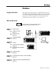
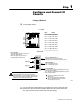
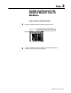
Install
keying bands.
See
the appropriate product data for the module
you are installing to determine the proper keying
positions for each module.
c
2
4
6
8
10
12
14
16
18
20
22
24
26
28
30
32
34
36
Keying
Bands
Backplane
Socket
10170-I
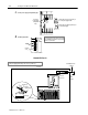
Set
the power supply configuration plug.
d
USING
POWER
SUPPLY
MODULE IN
THIS
CHASSIS?
I/O Chassis
Power Supply
Configuration
Plug
YN
Y
N
N
Y
Set this plug to the left (Y) position if you
use a slot power supply module.
Set this plug to the right (N) position if you
use an external supply.
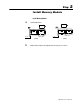
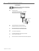
Ground I/O Chassis
Ground Bus
Enclosure
Grounding Electrode
Conductor
To
Earth
Ground
Processor
PLC2/30
When
using this grounding configuration, make no connections to EQUIP GND
on the power supply terminal strips. This can cause ground loops.
Ground Lug
Ground Lug
Star
Washer
Nut and
Captive Washer
I/O Chassis Wall