
User guide

Step 1
Publication
177210.1 - March 1996
Configure and Ground I/O
Chassis
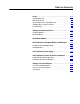
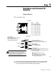
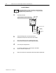
Configure I/O Chassis
If
you are using a power supply outside of the rack, plug the 9pin connector of the power cable
into the 9pin socket on the I/O chassis backplane and leave the other end of the power cable
loose. (Later
, you will connect this end of the cable to the power supply
.)
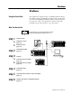
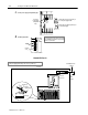
Set the backplane switches.
a
b
Switch
Group
Assembly
10183I
Input
Power
Socket
Rack: Switch:
123
1
2
3
4
5
6
7
on
off
on
on
on
on
on
on
on
on
on
on
on
off
off
off
off
off
off
off
off
Processor
Restart Lockout - 2
When ON, processor can restart I/O chassis
When OFF, I/O chassis must be restarted at the chassis.
Addressing Switch
- 5
ON 1slot addressing selected
OFF 2slot addressing selected
Last State Switch
When ON, outputs of this chassis remain in last
state when a fault is detected.
When OFF, outputs of this I/O chassis are
deenergized when a fault is detected.
Always OFF
Last Chassis Switch
- 8
ON Chassis does not contain the highest numbered I/O group
for the associated rack number
OFF Chassis does contain the highest numbered I/O group for
the associated rack number
If you have only a primary chassis, set this
switch to OFF.
If you have both primary and complementary
chassis, set the primary chassis to ON and the
complementary chassis to OFF.
10802I
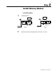
ATTENTION: Set switch 1 to the OFF position
to deenergize outputs wired to this chassis when a fault is
detected. If switch 1 is set to the ON position, outputs connected
to this chassis remain in their last state when a fault occurs and
machine motion may continue after fault detection.
O
O
12 3456 78
N
F
F
Always OFF
Local I/O
Remote I/O