
User guide

5–3
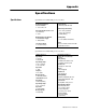
Install and Connect Remote I/O Scanner and Adapter
Publication
177210.1 - March 1996
d
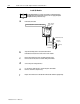
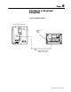
Install
the module.
front of chassis
lockingbar pins
Remove
power from the I/O chassis.
Pull
these pins to release the locking bar and swing it up.
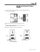
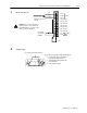
ATTENTION: Do not make connections to
terminals 4 through 10. These terminals are
connected
internally (1 to 4, 2 to 5 and 3
to 6) and
cannot
be used for any other purpose.
c
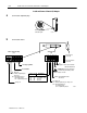
Wire
the field wiring arm.
1 Line 1
2 Shield
3 Line 2
4 No connection
5 No connection
6 No connection
7 No connection
8 No connection
9 No connection
10 No connection
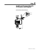
1
1 In
12 Ret
Reset
User supplied
I/O
rack restart
pushbutton
AllenBradley
Cable (cat. no.
1770CD)
Blue
Shield
Clear
1
2
3
4
5
6
7
8
9
10
11
12
Cable
17343
Remote I/O Cable
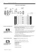
Insert the module, then snap the locking bar
over the top of the module to secure it.
Swing the field wiring arm up into place and
press until it latches.
Restore power to the system.