
User guide

5–2
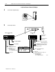
Install and Connect Remote I/O Scanner and Adapter
Publication
177210.1 - March 1996
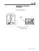
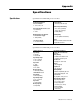
Install and Connect Remote I/O Adapter
a
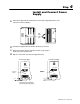
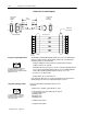
Set
the module switches.
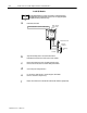
b
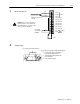
Set the module configuration plugs.
Position
all 3
jumpers
on the left 2 pins
10797I
12345678
O
N
O
F
F
O
N
O
F
F
1234
First I/O group number
I/O rack number
Address Switch Assembly
(S1)
Switch Assembly
(S2)
SD always OFF
SD2 without complementary I/O always OFF
SD2 with complementary I/O
ON Primary chassis
OFF Complementary chassis
Pressed in at top
Closed (ON)
Pressed in at bottom
Open (OFF)
Maximum I/O
chassis distance
SD always ON
SD2 without complementary I/O
always ON
SD2 with complementary I/O
ON Primary chassis
OFF Complementary chassis
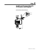
Always ON
56
Link Response ON for series B emulation
Scan on for all but last 4 slots
off for all slots
OFF for unrestricted
Switch Position
1 2
57.6K Baud 10,000ft
1
15.2K Baud 5,000ft
Not Used
Not Used
10798I
ATTENTION: Link response switch must
be ON when using the following scanner
modules: 1772SD2
ON OFF
OFF OFF
ON ON
ONOFF
Off