Allen Bradley PLC 2 Family Programmable Controllers product icon Quick Start for Experienced Users
Important User Information Because of the variety of uses for the products described in this publication, those responsible for the application and use of this control equipment must satisfy themselves that all necessary steps have been taken to assure that each application and use meets all performance and safety requirements, including any applicable laws, regulations, codes and standards.
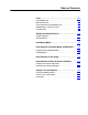
Table of Contents Preface . . . . . . . . . . . . . . . . . . . . . . . . . . . . . . . . . . . . . . . P-1 Using this Quick Start . . . . . . . . . . . . . . . . . . . . . . . . . . . . . . . . . What You Need to Do . . . . . . . . . . . . . . . . . . . . . . . . . . . . . . . . . System Components used in this Quick Start . . . . . . . . . . . . . . . . Installing in Class 1, Division 2 Locations . . . . . . . . . . . . . . . . . . . If You Need Help ... . . . . . . . . . . . . . . . . . . . . . . . .
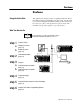
Preface Preface Using this Quick Start This quick start is designed to help you quickly install and connect a basic PLC-2 family programmable controller system. Use this guide if you are knowledgeable about PLC-2 family products but may not have used one or more of the products for a period of time. The information we provide is geared to “jog your memory.” What You Need to Do For more information...
P–2 Preface System Components used in this Quick Start Installing in Class 1, Division 2 Locations A B If You Need Help ... A B Publication 1772 10.
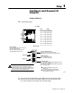
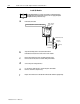
Step 1 Configure and Ground I/O Chassis Configure I/O Chassis a Set the backplane switches. Local I/O Rack: Switch Group Assembly Input Power Socket 10183 I 2 3 4 Always OFF 5 6 2 3 1 on on 2 on on off 3 on off on 4 5 on off off off on on 6 off on off 7 off off on 8 ATTENTION: Set switch 1 to the OFF position to deenergize outputs wired to this chassis when a fault is detected.
1–2 Configure and Ground I/O Chassis c Set the power supply configuration plug. YN I/O Chassis Power Supply Configuration Plug d Y N Install keying bands. Keying Bands Backplane Socket Y N USING POWER SUPPLY MODULE IN THIS CHASSIS? Set this plug to the left (Y) position if you use a slot power supply module. Set this plug to the right (N) position if you use an external supply.
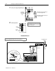
Step 2 Install Memory Module Install Memory Module a Install backup batteries. - - Alkaline Battery + 10120a I (alkaline) b - - + Orientation Alkaline Battery - + Battery Contacts 10120b I + Orientation Lithium Battery + Battery Contact (lithium) Install the memory module in the rightmost plastic slot of the processor chassis. Publication 1772 10.
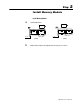
Step 3 Install and Connect I/O Adapter Module and I/O Modules Install and Connect I/O Adapter Module a Install the I/O adapter module in the left most slot of the I/O chassis. Module Locking Latch Use the locking latch to secure the module in place. PLC 2 I/O Adapter Module 10187 I b Connect the communication cable from the top socket of the I/O adapter to the I/O rack socket of the processor interface module. Publication 1772 10.
3–2 Install and Connect I/O Adapter Module and I/O Modules Install I/O Modules For more information... a Specific wiring information for each type of I/O module is contained in the product data publication for that specific module. Therefore, refer to the appropriate product data publication when you follow these steps. Install each I/O module. Use the locking latch to secure the module in place.
Step 4 Install and Connect Power Supply a Plug the power supply cable that extends from the rear of the power supply module into the socket on the processor chassis backplane. Power Supply Cable Socket b c d 0.5 AMP Fuse plug power cable in here 0.25 AMP Fuse Install the power supply module in the left most slot of the processor chassis. Plug the other end of the I/O power cable that you used in step 1b on page 1 1 into the power socket on the I/O chassis.
Step 5 Install and Connect Remote I/O Scanner and Adapter Install and Connect Remote I/O Scanner Blue Shield Clear Blue Shield Clear Channel A Channel B Publication 1772 10.
5–2 Install and Connect Remote I/O Scanner and Adapter Install and Connect Remote I/O Adapter a Set the module configuration plugs. Position all 3 jumpers on the left 2 pins b 10797 I Set the module switches.
Install and Connect Remote I/O Scanner and Adapter c Wire the field wiring arm. Blue Shield Remote I/O Cable Clear Allen Bradley Cable (cat. no. 1770 CD) ATTENTION: Do not make connections to terminals 4 through 10. These terminals are connected internally (1 to 4, 2 to 5 and 3 to 6) and cannot be used for any other purpose.
Step 6 Configure a Personal Computer Connect Programming Terminal PLC 2/20 on PLC 2/30 Processor PLC 2/30 Channel A PLC 2 Family Program Panel Interconnect Cable (cat. no. 1772 TC) Publication 1772 10.
6–2 Configure a Personal Computer Connect to a Personal Computer 62 pin D shell Connector Pin Male 10.2 cm (4 in.) 22 43 1 62 21 15 pin D shell Connector Pin Female 3.2 m (10.50 ft.) 10.2 cm (4 in.) 1784 CP2 cable 8 15 1 9 PLC 2 Processor Industrial Terminal 4 1 5 2 7 3 6 4 26 5 27 6 47 7 48 8 62 pin D shell Using 6200 Programming Software For more information...
Appendix Specifications Specifications Specifications for PLC-2/20 processors follow. Nominal Input Voltages to Processor Modules G +5.1V, +12V, 5.
I–2 Allen Bradley, a Rockwell Automation Business, has been helping its customers improve productivity and quality for more than 90 years. We design, manufacture and support a broad range of automation products worldwide. They include logic processors, power and motion control devices, operator interfaces, sensors and a variety of software. Rockwell is one of the world's leading technology companies. Worldwide representation.