
User Manual Owner's manual
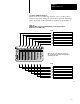

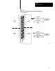
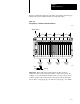
Table Of Contents
- 1772-6.5.8, Mini-PLC-2/02, -2/16, -2/17 Processor, User Manual
- Important User Information
- Summary of Changes
- Table of Contents
- 1 - Using This Manual
- 2 - Fundamentals of a Programmable Controller
- 3 - Hardware Features
- 4 - Installing Your Programmable Controller
- 5 - Starting Your Processor
- 6 - Maintaining and Troubleshooting Your Processor
- 7 - Memory Organization
- 8 - Scan Theory
- 9 - Relay-Like Instructions
- 10 - Program Control Instructions
- 11 - Timers and Counters
- 12 - Data Manipulation and Compare Instructions
- 13 - Three-Digit Math Instructions
- 14 - EAF Math Instructions
- 15 - EAF Log, Trig, and FIFO Instructions
- 16 - EAF Process Control Instructions
- 17 - Jump Instructions and Subroutines
- 18 - Block Transfer
- 19 - Data Transfer Instructions
- 20 - Bit Shift Registers
- 21 - Sequencers
- 22 - Selectable Timer Interrupts
- 23 - Report Generation
- 24 - Program Editing
- 25 - Programming Techniques
- 26 - Program Troubleshooting
- A - Specifications
- B - Processor Comparison Chart
- C - Number Systems
- D - Glossary
- E - Quick Reference
- Index
- Back Cover
Starting Your Processor
Chapter 5
5-17
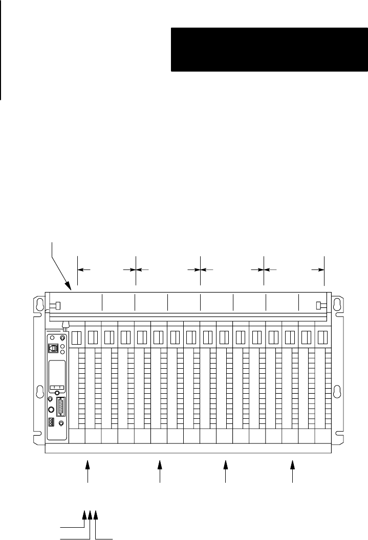
Figure 5.13 illustrates addressing 4 modules, each with the same I/O group
number, but in the four different racks of a single I/O chassis.
Figure 5.13
Group
Address of a Module in Four Different Racks
10337-I
03 47 03 47 03 47 03 47
15247
I/O group number
Rack 1 Rack 2 Rack 3 Rack 4
I/O group 1
address
1 1 1
input
rack I/O group
I/O group 1
address
1 2 1
I/O group 1
address
1 3 1
I/O group 1
address
1 4 1
Important: When addressing a block transfer module, it must be
addressed by the lowest group number that it occupies and at slot 0. For
example: a 1-slot block transfer module in rack 1, groups 2 and 3 (slot 2)
would be addressed (by rack-group-slot) at location 120. Be aware that
this module is occupying group 2, slots 0 and 1, and group 3, slots 0 and 1.