
User Manual Owner's manual
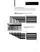

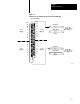
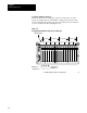
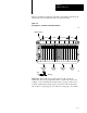
Table Of Contents
- 1772-6.5.8, Mini-PLC-2/02, -2/16, -2/17 Processor, User Manual
- Important User Information
- Summary of Changes
- Table of Contents
- 1 - Using This Manual
- 2 - Fundamentals of a Programmable Controller
- 3 - Hardware Features
- 4 - Installing Your Programmable Controller
- 5 - Starting Your Processor
- 6 - Maintaining and Troubleshooting Your Processor
- 7 - Memory Organization
- 8 - Scan Theory
- 9 - Relay-Like Instructions
- 10 - Program Control Instructions
- 11 - Timers and Counters
- 12 - Data Manipulation and Compare Instructions
- 13 - Three-Digit Math Instructions
- 14 - EAF Math Instructions
- 15 - EAF Log, Trig, and FIFO Instructions
- 16 - EAF Process Control Instructions
- 17 - Jump Instructions and Subroutines
- 18 - Block Transfer
- 19 - Data Transfer Instructions
- 20 - Bit Shift Registers
- 21 - Sequencers
- 22 - Selectable Timer Interrupts
- 23 - Report Generation
- 24 - Program Editing
- 25 - Programming Techniques
- 26 - Program Troubleshooting
- A - Specifications
- B - Processor Comparison Chart
- C - Number Systems
- D - Glossary
- E - Quick Reference
- Index
- Back Cover

Starting Your Processor
Chapter 5
5-14
1/2Slot Addressing
When you select 1/2-slot addressing, the processor addresses one-half of
an I/O module slot as one I/O group. The physical address of each I/O slot
corresponds to two input and two output image table words. The type of
module you install (8, 16 or 32 I/O points) determines the number of bits in
these words that are used.
With 1/2-slot addressing, since 32 input bits and 32 output bits are set aside
in the processor’s image table for each slot (16 input image table bits and
16 output image table bits times 2 groups per slot = 32 of each), you may
use any mix of I/O modules (8, 16 or 32 point) in the I/O chassis.
You select 1/2-slot addressing by setting switches 4 and 5 of the I/O
chassis backplane switch assembly:
Switch 4 to the ON position
Switch 5 to the ON position
Figure 5.11 illustrates the 1/2-slot addressing concept with a 32-point I/O
module. A 32-point I/O module (two 1/2-slot I/O groups) uses two input
or
two output words of the image table. I/O group applies to the upper 16
points; I/O group 1 applies to the lower 16 points.
You can use 8-point and 16-point I/O modules with 1/2-slot addressing but
the rest of the bits are unused. They may be addressed through either I/O
module group.
Important: For full compatibility with 1/2-slot addressing you must use a
series C, revision B (or later) 1770-T3 industrial terminal.