
User Manual Owner's manual
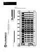
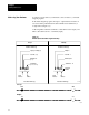
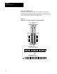
Table Of Contents
- 1772-6.5.8, Mini-PLC-2/02, -2/16, -2/17 Processor, User Manual
- Important User Information
- Summary of Changes
- Table of Contents
- 1 - Using This Manual
- 2 - Fundamentals of a Programmable Controller
- 3 - Hardware Features
- 4 - Installing Your Programmable Controller
- 5 - Starting Your Processor
- 6 - Maintaining and Troubleshooting Your Processor
- 7 - Memory Organization
- 8 - Scan Theory
- 9 - Relay-Like Instructions
- 10 - Program Control Instructions
- 11 - Timers and Counters
- 12 - Data Manipulation and Compare Instructions
- 13 - Three-Digit Math Instructions
- 14 - EAF Math Instructions
- 15 - EAF Log, Trig, and FIFO Instructions
- 16 - EAF Process Control Instructions
- 17 - Jump Instructions and Subroutines
- 18 - Block Transfer
- 19 - Data Transfer Instructions
- 20 - Bit Shift Registers
- 21 - Sequencers
- 22 - Selectable Timer Interrupts
- 23 - Report Generation
- 24 - Program Editing
- 25 - Programming Techniques
- 26 - Program Troubleshooting
- A - Specifications
- B - Processor Comparison Chart
- C - Number Systems
- D - Glossary
- E - Quick Reference
- Index
- Back Cover
Starting Your Processor
Chapter 5
5-7
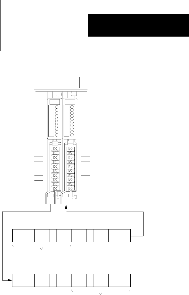
Figure 5.5
Illustration
of 2Slot Addressing with 8point Input and Output Modules
00
01
02
03
04
05
06
07
10
11
12
13
14
15
16
17
17 161514 12 10070605 03020100041113
17 161514 12 10070605 03020100041113
11868
input bits used
Output image table word
corresponding to the I/O group
Input image table word
corresponding to the I/O group
output bits used
input
terminals
2slot
I/O group
output
terminals
Using 16-Point I/O Modules
High-density (16-point) I/O modules provide 16 input terminals or 16
output terminals. 16-point I/O modules use a full word in the input or
output image table.
Important: 16-point modules may only be used in a complimentary
fashion in 2-slot addressing mode. Two 16-point modules, one input and
one output, can be used in a 2-slot I/O group (Figure 5.6).