
User Manual Owner's manual
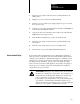
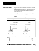
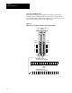
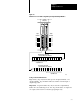
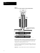
Table Of Contents
- 1772-6.5.8, Mini-PLC-2/02, -2/16, -2/17 Processor, User Manual
- Important User Information
- Summary of Changes
- Table of Contents
- 1 - Using This Manual
- 2 - Fundamentals of a Programmable Controller
- 3 - Hardware Features
- 4 - Installing Your Programmable Controller
- 5 - Starting Your Processor
- 6 - Maintaining and Troubleshooting Your Processor
- 7 - Memory Organization
- 8 - Scan Theory
- 9 - Relay-Like Instructions
- 10 - Program Control Instructions
- 11 - Timers and Counters
- 12 - Data Manipulation and Compare Instructions
- 13 - Three-Digit Math Instructions
- 14 - EAF Math Instructions
- 15 - EAF Log, Trig, and FIFO Instructions
- 16 - EAF Process Control Instructions
- 17 - Jump Instructions and Subroutines
- 18 - Block Transfer
- 19 - Data Transfer Instructions
- 20 - Bit Shift Registers
- 21 - Sequencers
- 22 - Selectable Timer Interrupts
- 23 - Report Generation
- 24 - Program Editing
- 25 - Programming Techniques
- 26 - Program Troubleshooting
- A - Specifications
- B - Processor Comparison Chart
- C - Number Systems
- D - Glossary
- E - Quick Reference
- Index
- Back Cover

Starting Your Processor
Chapter 5
5-5
In Figure 5.3, reading from left to right, the:
first number denotes the type of module:
-0 output
-1 input
second number denotes the I/O rack:
-In 2-slot addressing, the rack number is always 1.
-In 1-slot addressing, the rack number is either 1 or 2.
-In 1/2-slot addressing the rack number may be 1, 2, 3, or 4.
third number denotes an I/O group (0 to 7).
fourth and fifth numbers denote a terminal:
-In 2-slot addressing, 00 through 07 for the left slot of the I/O group,
10 through 17 for the right slot of the I/O group.
-In 1-slot addressing, 00 through 17 for each I/O group (slot).
-In 1/2-slot addressing, 00 through 17 for the upper half of each I/O
module (one group) and 00 through 17 for the lower half of each
module (another group).
2Slot
Addressing
The processor addresses two I/O module slots as one I/O group.
Each physical 2-slot I/O group is represented by a word in the input image
table and a word in the output image table. Each input terminal
corresponds to a bit in the input image table word and each output terminal
corresponds to a bit in the output image table word.
The maximum number of bits available for one 2-slot I/O group is 32: 16
bits in the input image table word and 16 bits in the output image table
word. The type of discrete I/O module you install, either 8-point (standard
density) or 16-point (high-density, used in complementary mode)
determines the number of bits in the words that are used.
You select 2-slot addressing by setting switches 4 and 5 of the I/O chassis
backplane switch assembly:
Switch 4 to the OFF position
Switch 5 to the OFF position