
User Manual Owner's manual
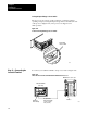
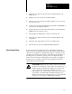
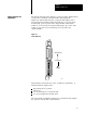
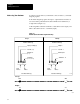
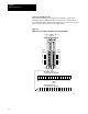
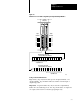
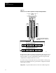
Table Of Contents
- 1772-6.5.8, Mini-PLC-2/02, -2/16, -2/17 Processor, User Manual
- Important User Information
- Summary of Changes
- Table of Contents
- 1 - Using This Manual
- 2 - Fundamentals of a Programmable Controller
- 3 - Hardware Features
- 4 - Installing Your Programmable Controller
- 5 - Starting Your Processor
- 6 - Maintaining and Troubleshooting Your Processor
- 7 - Memory Organization
- 8 - Scan Theory
- 9 - Relay-Like Instructions
- 10 - Program Control Instructions
- 11 - Timers and Counters
- 12 - Data Manipulation and Compare Instructions
- 13 - Three-Digit Math Instructions
- 14 - EAF Math Instructions
- 15 - EAF Log, Trig, and FIFO Instructions
- 16 - EAF Process Control Instructions
- 17 - Jump Instructions and Subroutines
- 18 - Block Transfer
- 19 - Data Transfer Instructions
- 20 - Bit Shift Registers
- 21 - Sequencers
- 22 - Selectable Timer Interrupts
- 23 - Report Generation
- 24 - Program Editing
- 25 - Programming Techniques
- 26 - Program Troubleshooting
- A - Specifications
- B - Processor Comparison Chart
- C - Number Systems
- D - Glossary
- E - Quick Reference
- Index
- Back Cover
Installing Your
Programmable Controller
Chapter 4
4-42
Setting
the Input V
oltage Selector Switch
The processors can operate on 120 or 220 V ac. Select the required
operating voltage by setting the Input Voltage Selector Switch at the rear
of the processor (Figure 4.24). The processor is shipped set for
120V operation.
Figure 4.24
Location
of the Input V
oltage Selector Switch
20216
input voltage
selector switch
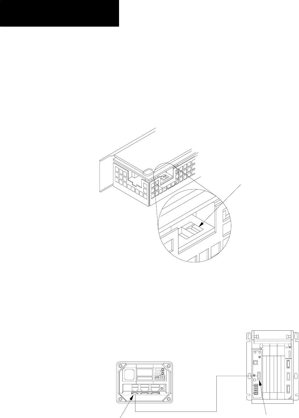
To connect your 1770-T3 terminal to the processor refer to Figure 4.25.
Figure 4.25
The
Connections between an Industrial T
erminal and a Processor
Channel A
Industrial Terminal
(rear view)
Program Panel
Interconnect Cable
Interface
MiniPLC2/02, 2/16, 2/17
PLC2 Family
10249
cat. no. 1772TC
10 ft (3.05 cm)
Step 12 - Connecting the
Industrial Terminal