
User Manual Owner's manual
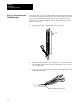
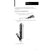
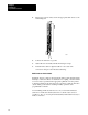
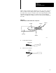
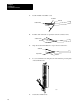
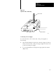
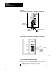
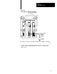
Table Of Contents
- 1772-6.5.8, Mini-PLC-2/02, -2/16, -2/17 Processor, User Manual
- Important User Information
- Summary of Changes
- Table of Contents
- 1 - Using This Manual
- 2 - Fundamentals of a Programmable Controller
- 3 - Hardware Features
- 4 - Installing Your Programmable Controller
- 5 - Starting Your Processor
- 6 - Maintaining and Troubleshooting Your Processor
- 7 - Memory Organization
- 8 - Scan Theory
- 9 - Relay-Like Instructions
- 10 - Program Control Instructions
- 11 - Timers and Counters
- 12 - Data Manipulation and Compare Instructions
- 13 - Three-Digit Math Instructions
- 14 - EAF Math Instructions
- 15 - EAF Log, Trig, and FIFO Instructions
- 16 - EAF Process Control Instructions
- 17 - Jump Instructions and Subroutines
- 18 - Block Transfer
- 19 - Data Transfer Instructions
- 20 - Bit Shift Registers
- 21 - Sequencers
- 22 - Selectable Timer Interrupts
- 23 - Report Generation
- 24 - Program Editing
- 25 - Programming Techniques
- 26 - Program Troubleshooting
- A - Specifications
- B - Processor Comparison Chart
- C - Number Systems
- D - Glossary
- E - Quick Reference
- Index
- Back Cover

Installing Your
Programmable Controller
Chapter 4
4-37
8. Repeat steps 6 and 7 until you wire the appropriate I/O devices to the
field wiring arm.
9. Connect the drain wire to ground.
10.Gather all of your wires and neatly bundle them using tie wraps.
11. Label all of your wires with a 5-digit I/O address code at each wire
connection. Chapter 7 describes I/O addressing.
12.Make sure that the field wiring arm pivots freely from vertical
to horizontal.
13.Replace the field wiring arm’s terminal cover.
14.Write terminal numbers on the labels next to the terminal’s status
indicator and on the terminal cover. These notes aid you during
system start-up (chapter 5) and troubleshooting (Chapter 6).
If your application uses many shielded cables connected to one I/O
chassis, then:
provide a ground bus to connect the shielded wires
solder several drain wires together at a field wiring arm so you route
only one drain
When ac power is supplied as a separately derived system through an
isolation or step-down transformer, you can connect the transformer either
as a grounded or an ungrounded ac system.
If you want to connect: Then:
a grounded ac system connect one side of the transformer secondary to the
ground bus (Figure 4.1)
an ungrounded ac system connect one side of each test switch for the groundfault
detector lights to the ground bus (Figure 4.2)
Power supplies are designed to give an ac undervoltage signal that shuts
the processor down when ac line voltage drops below a specific value
(Table 4.E). Power supplies give an ac OK signal that turns the processor
on when the line voltage rises above a specific value (Table 4.E). This
shutdown feature helps keep invalid data out of memory.
Step
1
1 - Connecting Power
to the Processor or
Power Supply