
User Manual Owner's manual
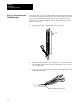
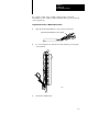
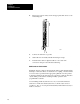
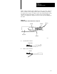
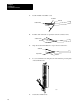
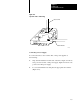
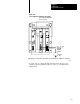
Table Of Contents
- 1772-6.5.8, Mini-PLC-2/02, -2/16, -2/17 Processor, User Manual
- Important User Information
- Summary of Changes
- Table of Contents
- 1 - Using This Manual
- 2 - Fundamentals of a Programmable Controller
- 3 - Hardware Features
- 4 - Installing Your Programmable Controller
- 5 - Starting Your Processor
- 6 - Maintaining and Troubleshooting Your Processor
- 7 - Memory Organization
- 8 - Scan Theory
- 9 - Relay-Like Instructions
- 10 - Program Control Instructions
- 11 - Timers and Counters
- 12 - Data Manipulation and Compare Instructions
- 13 - Three-Digit Math Instructions
- 14 - EAF Math Instructions
- 15 - EAF Log, Trig, and FIFO Instructions
- 16 - EAF Process Control Instructions
- 17 - Jump Instructions and Subroutines
- 18 - Block Transfer
- 19 - Data Transfer Instructions
- 20 - Bit Shift Registers
- 21 - Sequencers
- 22 - Selectable Timer Interrupts
- 23 - Report Generation
- 24 - Program Editing
- 25 - Programming Techniques
- 26 - Program Troubleshooting
- A - Specifications
- B - Processor Comparison Chart
- C - Number Systems
- D - Glossary
- E - Quick Reference
- Index
- Back Cover
Installing Your
Programmable Controller
Chapter 4
4-32
Your I/O devices connect to the I/O module’s field wiring arm. Every I/O
module must be properly wired and every I/O connection must be made at
the proper field wiring arm terminal. Refer to the specific I/O module
publication for connection diagrams. We recommend using copper wire
for these connections.
1. Grasp the lug and open the terminal cover to the right.
lug
2. Measure the wire distance from your I/O devices to the field wiring
arm terminals. This distance determines the length of wire you need
for your application.
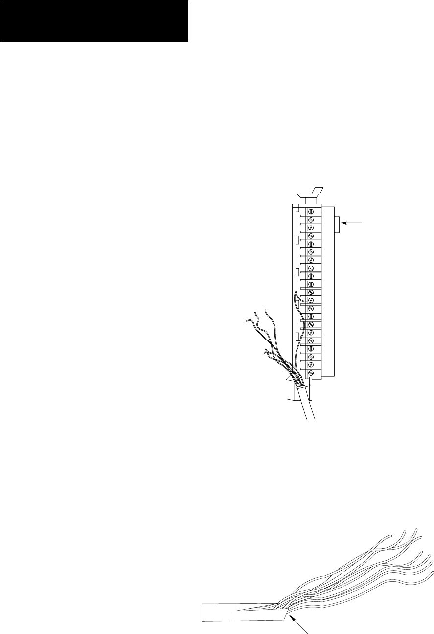
3. Strip some of the outer jacket from the end of the cable that connects
to the field wiring arm.
Strip some casing to expose the wires
Step 10 - Connecting to the
Field W
iring Arms