
User Manual Owner's manual
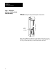
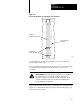
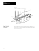
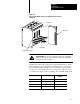
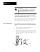
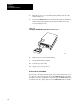
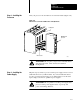
Table Of Contents
- 1772-6.5.8, Mini-PLC-2/02, -2/16, -2/17 Processor, User Manual
- Important User Information
- Summary of Changes
- Table of Contents
- 1 - Using This Manual
- 2 - Fundamentals of a Programmable Controller
- 3 - Hardware Features
- 4 - Installing Your Programmable Controller
- 5 - Starting Your Processor
- 6 - Maintaining and Troubleshooting Your Processor
- 7 - Memory Organization
- 8 - Scan Theory
- 9 - Relay-Like Instructions
- 10 - Program Control Instructions
- 11 - Timers and Counters
- 12 - Data Manipulation and Compare Instructions
- 13 - Three-Digit Math Instructions
- 14 - EAF Math Instructions
- 15 - EAF Log, Trig, and FIFO Instructions
- 16 - EAF Process Control Instructions
- 17 - Jump Instructions and Subroutines
- 18 - Block Transfer
- 19 - Data Transfer Instructions
- 20 - Bit Shift Registers
- 21 - Sequencers
- 22 - Selectable Timer Interrupts
- 23 - Report Generation
- 24 - Program Editing
- 25 - Programming Techniques
- 26 - Program Troubleshooting
- A - Specifications
- B - Processor Comparison Chart
- C - Number Systems
- D - Glossary
- E - Quick Reference
- Index
- Back Cover
Installing Your
Programmable Controller
Chapter 4
4-31
Slide your processor into the leftmost slot of the I/O chassis (Figure 4.18)
Figure 4.18
Place
the Processor in the LeftMost Slot of the I/O Chassis
20215
locking bar
leftmost slot
MiniPLC2/17
processor
ATTENTION: Do not place your processor in the I/O chassis
without keying bands. Short circuits can result from
misalignment.
Skip this step if you have a processor with a power supply and do not need
additional current for your I/O modules. If you need additional current,
use an ac powered supply because we recommend that you use the same
input voltage source for two paralleled power supplies
ATTENTION: Do not parallel a 1771-P5 power supply and a
processor with a power supply because of power-up and
power-down timing difference.
Step 8 - Installing the
Processor
Step 9 - Installing the
Power Supply