
User Manual Owner's manual
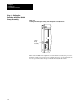
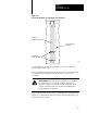
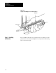
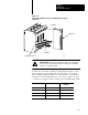
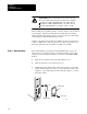
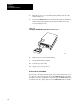
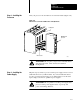
Table Of Contents
- 1772-6.5.8, Mini-PLC-2/02, -2/16, -2/17 Processor, User Manual
- Important User Information
- Summary of Changes
- Table of Contents
- 1 - Using This Manual
- 2 - Fundamentals of a Programmable Controller
- 3 - Hardware Features
- 4 - Installing Your Programmable Controller
- 5 - Starting Your Processor
- 6 - Maintaining and Troubleshooting Your Processor
- 7 - Memory Organization
- 8 - Scan Theory
- 9 - Relay-Like Instructions
- 10 - Program Control Instructions
- 11 - Timers and Counters
- 12 - Data Manipulation and Compare Instructions
- 13 - Three-Digit Math Instructions
- 14 - EAF Math Instructions
- 15 - EAF Log, Trig, and FIFO Instructions
- 16 - EAF Process Control Instructions
- 17 - Jump Instructions and Subroutines
- 18 - Block Transfer
- 19 - Data Transfer Instructions
- 20 - Bit Shift Registers
- 21 - Sequencers
- 22 - Selectable Timer Interrupts
- 23 - Report Generation
- 24 - Program Editing
- 25 - Programming Techniques
- 26 - Program Troubleshooting
- A - Specifications
- B - Processor Comparison Chart
- C - Number Systems
- D - Glossary
- E - Quick Reference
- Index
- Back Cover
Installing Your
Programmable Controller
Chapter 4
4-30
6. Place the processor on a clean flat surface with the bottom of the
module facing you.
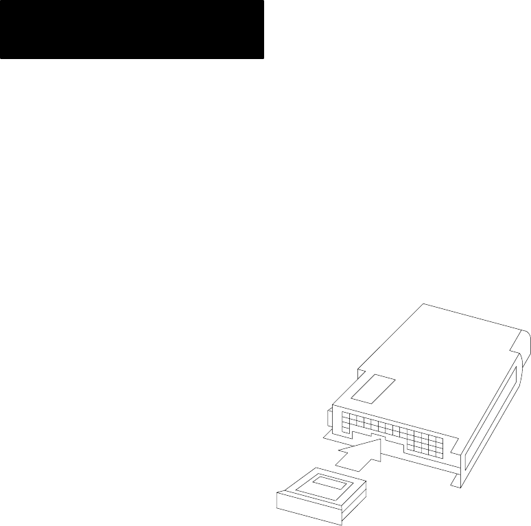
7. Position the EEPROM memory module in the memory module slot
with its label facing upward. Insert and press firmly for proper
connection (Figure 4.17).
Figure 4.17
Inserting
the EEPROM Memory Module into the Processor
10316-I
8. Slide the processor into the I/O chassis.
9. Secure the I/O chassis latches.
10. Connect the power cable.
11. Apply power to the processor
How to Remove the EEPROM
Repeat steps 1 through 4 from the previous procedure, then insert a coin
into the slot so that it engages the lip on the EEPROM memory module.
Carefully rotate the coin upward to start removing the EEPROM memory
module from its slot. Grasp and remove the EEPROM memory module.