
User Manual Owner's manual
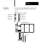
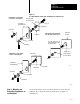
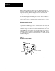
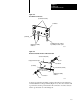
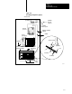
Table Of Contents
- 1772-6.5.8, Mini-PLC-2/02, -2/16, -2/17 Processor, User Manual
- Important User Information
- Summary of Changes
- Table of Contents
- 1 - Using This Manual
- 2 - Fundamentals of a Programmable Controller
- 3 - Hardware Features
- 4 - Installing Your Programmable Controller
- 5 - Starting Your Processor
- 6 - Maintaining and Troubleshooting Your Processor
- 7 - Memory Organization
- 8 - Scan Theory
- 9 - Relay-Like Instructions
- 10 - Program Control Instructions
- 11 - Timers and Counters
- 12 - Data Manipulation and Compare Instructions
- 13 - Three-Digit Math Instructions
- 14 - EAF Math Instructions
- 15 - EAF Log, Trig, and FIFO Instructions
- 16 - EAF Process Control Instructions
- 17 - Jump Instructions and Subroutines
- 18 - Block Transfer
- 19 - Data Transfer Instructions
- 20 - Bit Shift Registers
- 21 - Sequencers
- 22 - Selectable Timer Interrupts
- 23 - Report Generation
- 24 - Program Editing
- 25 - Programming Techniques
- 26 - Program Troubleshooting
- A - Specifications
- B - Processor Comparison Chart
- C - Number Systems
- D - Glossary
- E - Quick Reference
- Index
- Back Cover

Installing Your
Programmable Controller
Chapter 4
4-20
If the power supply has its own groundable chassis, do not connect the
GND terminal of the power supply. However, when you connect power to
a power supply without a groundable chassis of its own (such as an
ac-input power-supply module), you must also use 12 AWG copper wire to
connect its GND terminal to the ground stud or mounting bolt connected to
the ground bus (Figure 4.12).
Do not lay one ground lug directly on top of the other; this type of
connection can become loose due to compression op f the metal lugs.
Sandwich the first lug between a star washer and a nut with a captured star
washer. After tightening the nut, sandwich the second lug between the first
nut and a second nut with a captive star washer (Figure 4.12).
GroundingElectrode Conductor
Connect the ground bus to the grounding-electrode system through a
grounding-electrode conductor. The grounding-electrode system is at
earth-ground potential and is the central ground for all electrical equipment
and ac power within any facility. Use 8 AWG copper wire minimum for
the grounding-electrode conductor to guard against EMI. The National
Electrical Code specifies safety requirements for the
grounding-electrode conductor.
Shielded
Cables
Certain connections require shielded cables to help reduce the effects of
electrical noise coupling. Ground each shield at one end only. A shield
grounded at both ends forms a ground loop which could cause faulty
processor operation.
Ground each shield at the end specified in the appropriate publication for
the product.
Avoid breaking shields at junction boxes. Many type of connectors for
shielded conductors are available from various manufacturers. If you do
break a shield at a junction box:
Connect only category-2 conductors in the junction box.
Do not strip the shield back any further than necessary to make
a connection
Connect the shields of the two cable segments to ensure continuity
along the entire length of the cable.