
User Manual Owner's manual
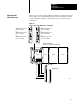
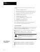
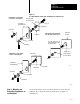
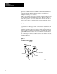
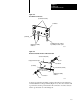
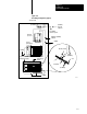
Table Of Contents
- 1772-6.5.8, Mini-PLC-2/02, -2/16, -2/17 Processor, User Manual
- Important User Information
- Summary of Changes
- Table of Contents
- 1 - Using This Manual
- 2 - Fundamentals of a Programmable Controller
- 3 - Hardware Features
- 4 - Installing Your Programmable Controller
- 5 - Starting Your Processor
- 6 - Maintaining and Troubleshooting Your Processor
- 7 - Memory Organization
- 8 - Scan Theory
- 9 - Relay-Like Instructions
- 10 - Program Control Instructions
- 11 - Timers and Counters
- 12 - Data Manipulation and Compare Instructions
- 13 - Three-Digit Math Instructions
- 14 - EAF Math Instructions
- 15 - EAF Log, Trig, and FIFO Instructions
- 16 - EAF Process Control Instructions
- 17 - Jump Instructions and Subroutines
- 18 - Block Transfer
- 19 - Data Transfer Instructions
- 20 - Bit Shift Registers
- 21 - Sequencers
- 22 - Selectable Timer Interrupts
- 23 - Report Generation
- 24 - Program Editing
- 25 - Programming Techniques
- 26 - Program Troubleshooting
- A - Specifications
- B - Processor Comparison Chart
- C - Number Systems
- D - Glossary
- E - Quick Reference
- Index
- Back Cover
Installing Your
Programmable Controller
Chapter 4
4-19
Figure 4.10
Ground
Bus Connections
10309-I
ground bus
ground lug
ground bus mounting
equipment grounding
conductors
grounding electrode conductor
to grounding electrode system
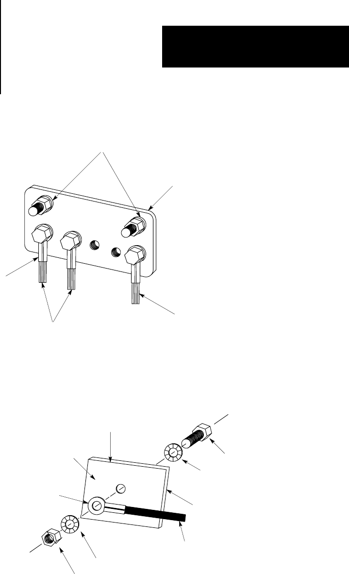
Figure 4.11
Details
of Ground Connection at Enclosure W
all
10310-I
enclosure wall (inside)
ground lug
scrape paint on both sides
nut
star washer
equipment grounding
conductor
enclosure wall (outside)
star washer
bolt
Connect an equipment grounding conductor directly from each chassis to
an individual bolt on the ground bus (Figure 4.12). For those chassis with
a ground stud, use the ground stud for this connection. For those chassis
with no ground stud, use a mounting bolt.