
User Manual Owner's manual
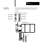
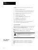
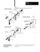
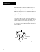
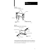
Table Of Contents
- 1772-6.5.8, Mini-PLC-2/02, -2/16, -2/17 Processor, User Manual
- Important User Information
- Summary of Changes
- Table of Contents
- 1 - Using This Manual
- 2 - Fundamentals of a Programmable Controller
- 3 - Hardware Features
- 4 - Installing Your Programmable Controller
- 5 - Starting Your Processor
- 6 - Maintaining and Troubleshooting Your Processor
- 7 - Memory Organization
- 8 - Scan Theory
- 9 - Relay-Like Instructions
- 10 - Program Control Instructions
- 11 - Timers and Counters
- 12 - Data Manipulation and Compare Instructions
- 13 - Three-Digit Math Instructions
- 14 - EAF Math Instructions
- 15 - EAF Log, Trig, and FIFO Instructions
- 16 - EAF Process Control Instructions
- 17 - Jump Instructions and Subroutines
- 18 - Block Transfer
- 19 - Data Transfer Instructions
- 20 - Bit Shift Registers
- 21 - Sequencers
- 22 - Selectable Timer Interrupts
- 23 - Report Generation
- 24 - Program Editing
- 25 - Programming Techniques
- 26 - Program Troubleshooting
- A - Specifications
- B - Processor Comparison Chart
- C - Number Systems
- D - Glossary
- E - Quick Reference
- Index
- Back Cover
Installing Your
Programmable Controller
Chapter 4
4-18
If the mounting brackets of a chassis do not lay flat before the nuts are
tightened, use additional washers as shims so that the chassis will not be
warped by tightening the nuts. Warping a chassis could damage the
backplane and cause poor connections.
Make good electrical connection between each chassis, the backpanel, and
the enclosure through each mounting bolt or stud. Wherever contact is
made, remove paint or other non-conductive finish from around studs or
tapped holes so that good electrical contact is made at each bolt or stud.
Equipment Ground Conductor
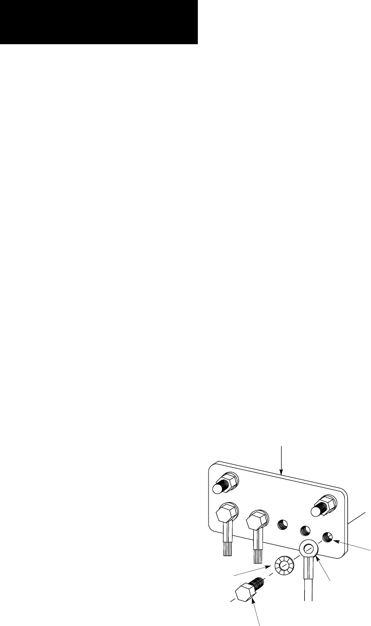
In addition to the connection through each bolt or stud, use either 1-inch
copper braid or 8 AWG copper wire to connect between each chassis, the
enclosure, and a central ground but mounted on the backpanel. Figure 4.9
and Figure 4.10 show ground-bus connection details. Figure 4.11 shows
enclosure-wall ground connection details. Use a steel enclosure to guard
against EMI. If the enclosure door has a viewing window, it should be a
laminated screen or a conductive optical substrate to block EMI. Do not
rely on the hinge for electrical contact between the door and the enclosure;
install a bonding wire.
Figure 4.9
Ground
Bus Connection Details
10308-I
ground bus
tapped hole
ground lug
bolt
star washer