
User Manual Owner's manual
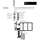
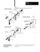
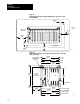
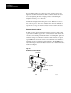
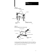
Table Of Contents
- 1772-6.5.8, Mini-PLC-2/02, -2/16, -2/17 Processor, User Manual
- Important User Information
- Summary of Changes
- Table of Contents
- 1 - Using This Manual
- 2 - Fundamentals of a Programmable Controller
- 3 - Hardware Features
- 4 - Installing Your Programmable Controller
- 5 - Starting Your Processor
- 6 - Maintaining and Troubleshooting Your Processor
- 7 - Memory Organization
- 8 - Scan Theory
- 9 - Relay-Like Instructions
- 10 - Program Control Instructions
- 11 - Timers and Counters
- 12 - Data Manipulation and Compare Instructions
- 13 - Three-Digit Math Instructions
- 14 - EAF Math Instructions
- 15 - EAF Log, Trig, and FIFO Instructions
- 16 - EAF Process Control Instructions
- 17 - Jump Instructions and Subroutines
- 18 - Block Transfer
- 19 - Data Transfer Instructions
- 20 - Bit Shift Registers
- 21 - Sequencers
- 22 - Selectable Timer Interrupts
- 23 - Report Generation
- 24 - Program Editing
- 25 - Programming Techniques
- 26 - Program Troubleshooting
- A - Specifications
- B - Processor Comparison Chart
- C - Number Systems
- D - Glossary
- E - Quick Reference
- Index
- Back Cover
Installing Your
Programmable Controller
Chapter 4
4-16
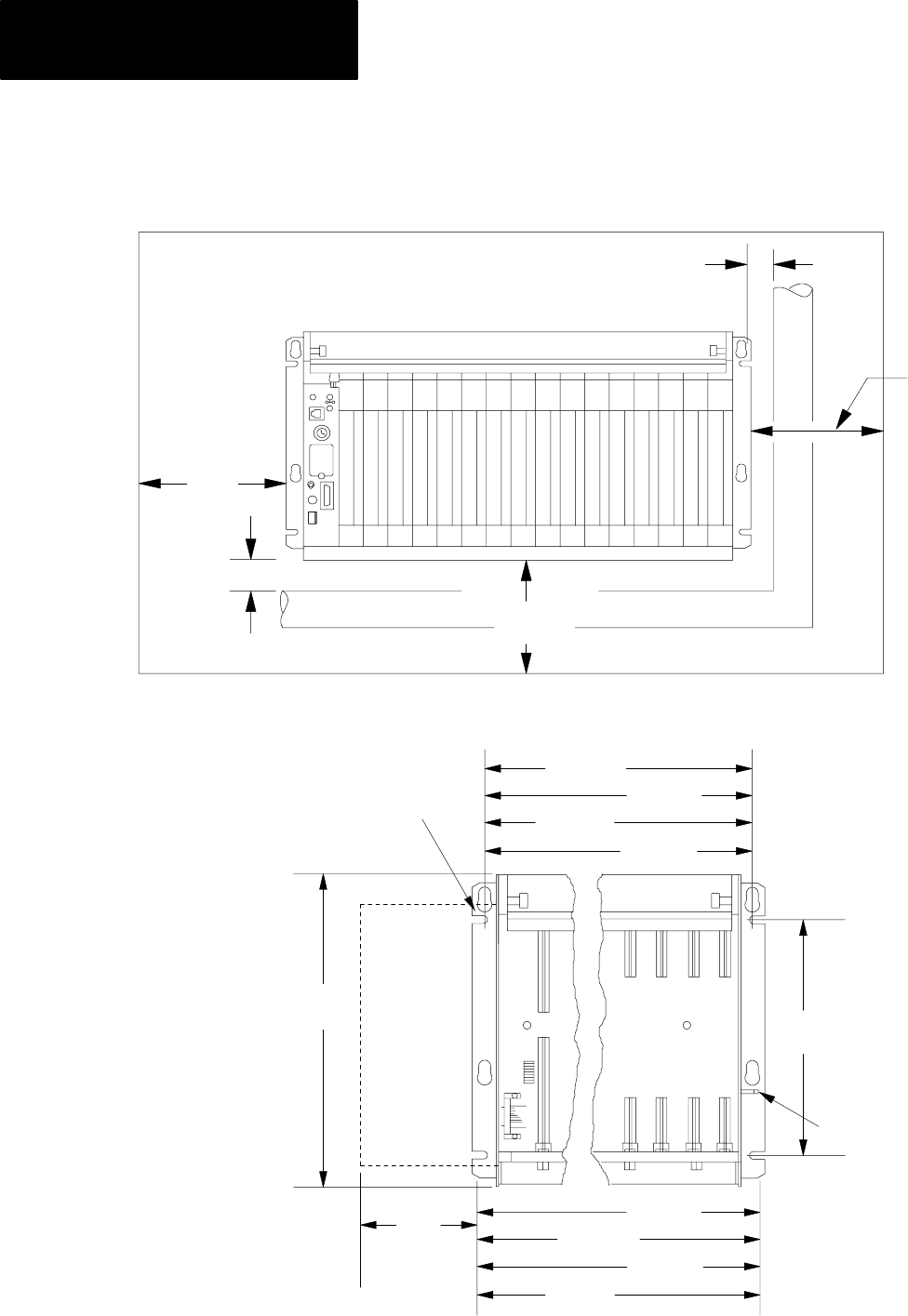
Figure 4.7
Programmable
Controller Components Must Not be Spaced Less Than
These Minimums
12059
50.8mm
(2)
101.6mm
(4)
50.8mm
(2)
101.6mm
(4)
Wiring Duct
MiniPLC2
Processor
152.4mm
(6)
Figure 4.8
Y
ou Need These Dimensions to Mount an I/O Chassis (cat.no. 1771A1B,
A2B, A3B, A4B)
16slot
12slot
8slot
4slot
16slot 1771A4B
12slot 1771A3B1
8slot 1771A2B
4slot 1771A1B
16189
ground stud
1771P2 or
1771P7
power supply
315mm
(12.41)
92mm
(3.6)
610mm
(24.01)
483mm
(19.01)
356mm
(14.01)
247mm
(9)
594mm
(23.4)
476mm
(18.4)
340mm
(13.4)
213mm
(8.4)
use .25 diameter
mounting bolts
(4 places)
254mm
(10)