
User Manual Owner's manual
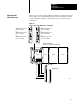
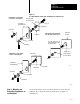
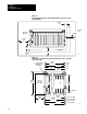
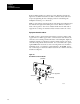
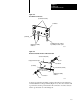
Table Of Contents
- 1772-6.5.8, Mini-PLC-2/02, -2/16, -2/17 Processor, User Manual
- Important User Information
- Summary of Changes
- Table of Contents
- 1 - Using This Manual
- 2 - Fundamentals of a Programmable Controller
- 3 - Hardware Features
- 4 - Installing Your Programmable Controller
- 5 - Starting Your Processor
- 6 - Maintaining and Troubleshooting Your Processor
- 7 - Memory Organization
- 8 - Scan Theory
- 9 - Relay-Like Instructions
- 10 - Program Control Instructions
- 11 - Timers and Counters
- 12 - Data Manipulation and Compare Instructions
- 13 - Three-Digit Math Instructions
- 14 - EAF Math Instructions
- 15 - EAF Log, Trig, and FIFO Instructions
- 16 - EAF Process Control Instructions
- 17 - Jump Instructions and Subroutines
- 18 - Block Transfer
- 19 - Data Transfer Instructions
- 20 - Bit Shift Registers
- 21 - Sequencers
- 22 - Selectable Timer Interrupts
- 23 - Report Generation
- 24 - Program Editing
- 25 - Programming Techniques
- 26 - Program Troubleshooting
- A - Specifications
- B - Processor Comparison Chart
- C - Number Systems
- D - Glossary
- E - Quick Reference
- Index
- Back Cover
Installing Your
Programmable Controller
Chapter 4
4-13
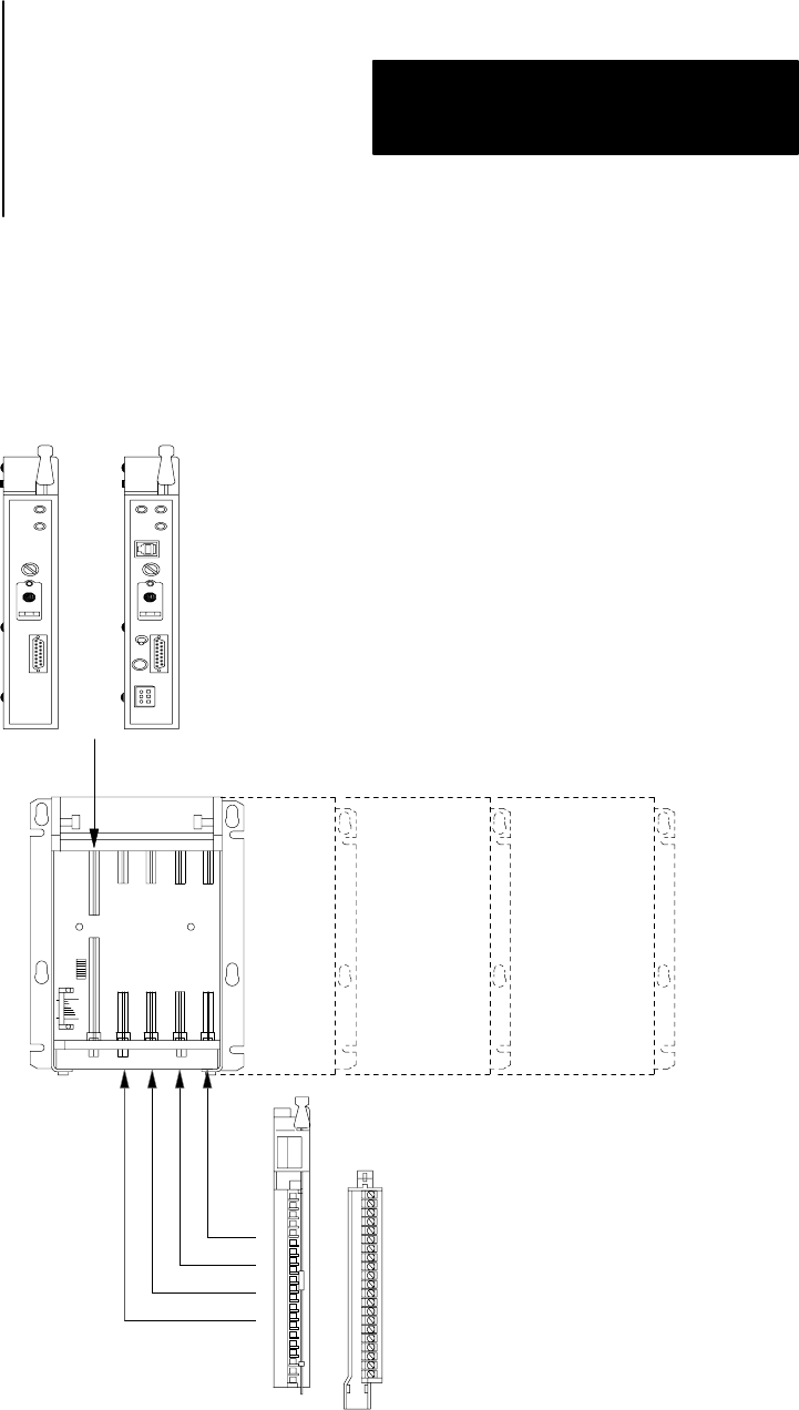
This section provides general installation guidelines. The input and output
devices that control your manufacturing operations determine the specifics
of your installation. Figure 4.5 shows the location of your major pieces
of hardware.
Figure 4.5
The
Locations of the Major Pieces of Hardware
13491
or
I/O module
field wiring arm
I/O Chassis Assembly
(Cat. No. 1771A1B, A2B, A3B, A4B)
MiniPLC2/02 processor
(cat. no. 1772LZ)
or
MiniPLC2/16 processor
(cat. no. 1772LX)
or
MiniPLC2/17 processor
(cat. no. 1772LW)
MiniPLC2/02 processor
(cat. no. 1772LZP)
or
MiniPLC2/16 processor
(cat. no. 1772LXP)
or
MiniPLC2/17 processor
(cat. no. 1772LWP)
4slot 8slot 12slot 16slot
How to Install
Your Processor