
User Manual Owner's manual
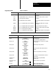
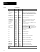
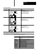
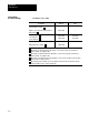
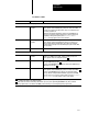
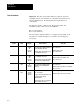
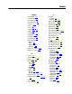
Table Of Contents
- 1772-6.5.8, Mini-PLC-2/02, -2/16, -2/17 Processor, User Manual
- Important User Information
- Summary of Changes
- Table of Contents
- 1 - Using This Manual
- 2 - Fundamentals of a Programmable Controller
- 3 - Hardware Features
- 4 - Installing Your Programmable Controller
- 5 - Starting Your Processor
- 6 - Maintaining and Troubleshooting Your Processor
- 7 - Memory Organization
- 8 - Scan Theory
- 9 - Relay-Like Instructions
- 10 - Program Control Instructions
- 11 - Timers and Counters
- 12 - Data Manipulation and Compare Instructions
- 13 - Three-Digit Math Instructions
- 14 - EAF Math Instructions
- 15 - EAF Log, Trig, and FIFO Instructions
- 16 - EAF Process Control Instructions
- 17 - Jump Instructions and Subroutines
- 18 - Block Transfer
- 19 - Data Transfer Instructions
- 20 - Bit Shift Registers
- 21 - Sequencers
- 22 - Selectable Timer Interrupts
- 23 - Report Generation
- 24 - Program Editing
- 25 - Programming Techniques
- 26 - Program Troubleshooting
- A - Specifications
- B - Processor Comparison Chart
- C - Number Systems
- D - Glossary
- E - Quick Reference
- Index
- Back Cover

Quick Reference
Appendix E
E-34
Important: The timer word address, XXX, is assigned to the timer
accumulated areas of the data table. To determine which addresses are
valid accumulated areas, the third digit from the right must be an
even number.
The time base 1.0, 0.1 or 0.01 second. Preset values, YYY, and
accumulated values, ZZZ, can vary from 000-999.
Bit 15 is the timed bit.
Bit 17 is the enable bit.
The word address displayed will be 3 or 4 digits long depending on the
data table size. When entering the word address, use a leading zero
if necessary.
Key
Symbol
Instruction
Name
1770T3
Display
Rung Conditions Status Bits
-(TON)- Timer On Delay XXX
-(TON)-
TB
PR YYY
AC ZZZ
When the rung is true, the timer begins
to increment the accumulated value at a
rate specified by the time base.
When the rung is false, the timer resets
the accumulated value to 000.
When the rung is true and AC = PR:
bits 15 and 17 set
When the rung is false:
bits 15 and 17 reset
-(TOF)- Timer Off Delay XXX
-(TOF)-
TB
PR YYY
AC ZZZ
When the rung is true, the timer resets
the accumulated value to 000.
When the rung is false, the timer begins
to increment the accumulated value.
When the rung is true: bits 15, 17 are set
When the rung is false and AC = PR:
bits 15 and 17 reset
-(RTO)- Retentive
Timer
-(RTO)-
TB
PR YYY
AC ZZZ
When the rung is true, the timer begins
to increment the accumulated value.
When false, the accumulated value
is retained.
When the rung is true and AC = PR:
bits 15 and 17 set
When the rung is false: bit 15 no action taken,
but bit 17 is reset
-(RTR)- Retentive
Timer
XXX
-(RTR)-
PR YYY
AC ZZZ
XXX - Word address of the retentive
timer. It is resetting.
The preset and accumulated values are
automatically entered by the
industrial terminal.
When the rung is true,t he accumulated
value and status bits are reset.
When the rung is true: bits 15 and 17 are reset
When the rung is false: no action is taken
Timer Instructions