
User Manual Owner's manual
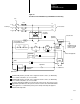
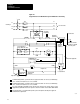
Table Of Contents
- 1772-6.5.8, Mini-PLC-2/02, -2/16, -2/17 Processor, User Manual
- Important User Information
- Summary of Changes
- Table of Contents
- 1 - Using This Manual
- 2 - Fundamentals of a Programmable Controller
- 3 - Hardware Features
- 4 - Installing Your Programmable Controller
- 5 - Starting Your Processor
- 6 - Maintaining and Troubleshooting Your Processor
- 7 - Memory Organization
- 8 - Scan Theory
- 9 - Relay-Like Instructions
- 10 - Program Control Instructions
- 11 - Timers and Counters
- 12 - Data Manipulation and Compare Instructions
- 13 - Three-Digit Math Instructions
- 14 - EAF Math Instructions
- 15 - EAF Log, Trig, and FIFO Instructions
- 16 - EAF Process Control Instructions
- 17 - Jump Instructions and Subroutines
- 18 - Block Transfer
- 19 - Data Transfer Instructions
- 20 - Bit Shift Registers
- 21 - Sequencers
- 22 - Selectable Timer Interrupts
- 23 - Report Generation
- 24 - Program Editing
- 25 - Programming Techniques
- 26 - Program Troubleshooting
- A - Specifications
- B - Processor Comparison Chart
- C - Number Systems
- D - Glossary
- E - Quick Reference
- Index
- Back Cover
Installing Your
Programmable Controller
Chapter 4
4-8
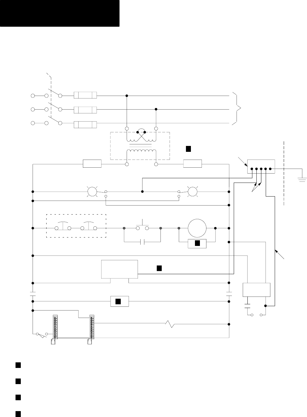
Figure 4.2
Ungrounded ac PowerDistribution System with Master Control Relay
L1
L2
L3
1FU
2FU
3FU
H
FUSE
L1
L2
L3
H
+–
10301
LN1
1
4
H
3
H
2
X
1
X
2
1
2
3
4
FUSE
1
2
3
4
1LT
2LT
To minimize EMI generation, you should connect a suppression network: for 120V ac, use AllenBradley
cat. no. 700N24; for 220/240V ac, use cat. no. 599KA04.
To minimize EMI generation, you should connect a suppression network: for 120V ac, use AllenBradley
cat. no. 700N24; for 220/240V ac, use cat. no. 599KA04.
For a power supply with a groundable chassis, this represents connection to the chassis only. For a power
supply without a groundable chassis, this represents connection to both the chassis and the GND terminal.
In many applications, a second transformer provides power to the input circuits and power supplies for
isolation from the output circuits.
output module
wiring arm
input module
wiring arm
input device
output device
use any number of
Estop switches in series
CRM
I/O chassis
power supply
start
to motor starters
enclosure wall
grounding electrode
conductor to groundi
electrode system
grounding
electrode
conductors
connect when applicable
backpanel
ground bus
stepdown
transformer
CRM
CRM
CRM
CRM
GND
incoming ac
disc
user dc
supply
to dc I/O devices