
User Manual Owner's manual
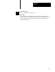
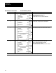
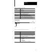
Table Of Contents
- 1772-6.5.8, Mini-PLC-2/02, -2/16, -2/17 Processor, User Manual
- Important User Information
- Summary of Changes
- Table of Contents
- 1 - Using This Manual
- 2 - Fundamentals of a Programmable Controller
- 3 - Hardware Features
- 4 - Installing Your Programmable Controller
- 5 - Starting Your Processor
- 6 - Maintaining and Troubleshooting Your Processor
- 7 - Memory Organization
- 8 - Scan Theory
- 9 - Relay-Like Instructions
- 10 - Program Control Instructions
- 11 - Timers and Counters
- 12 - Data Manipulation and Compare Instructions
- 13 - Three-Digit Math Instructions
- 14 - EAF Math Instructions
- 15 - EAF Log, Trig, and FIFO Instructions
- 16 - EAF Process Control Instructions
- 17 - Jump Instructions and Subroutines
- 18 - Block Transfer
- 19 - Data Transfer Instructions
- 20 - Bit Shift Registers
- 21 - Sequencers
- 22 - Selectable Timer Interrupts
- 23 - Report Generation
- 24 - Program Editing
- 25 - Programming Techniques
- 26 - Program Troubleshooting
- A - Specifications
- B - Processor Comparison Chart
- C - Number Systems
- D - Glossary
- E - Quick Reference
- Index
- Back Cover
Quick Reference
Appendix E
E-5
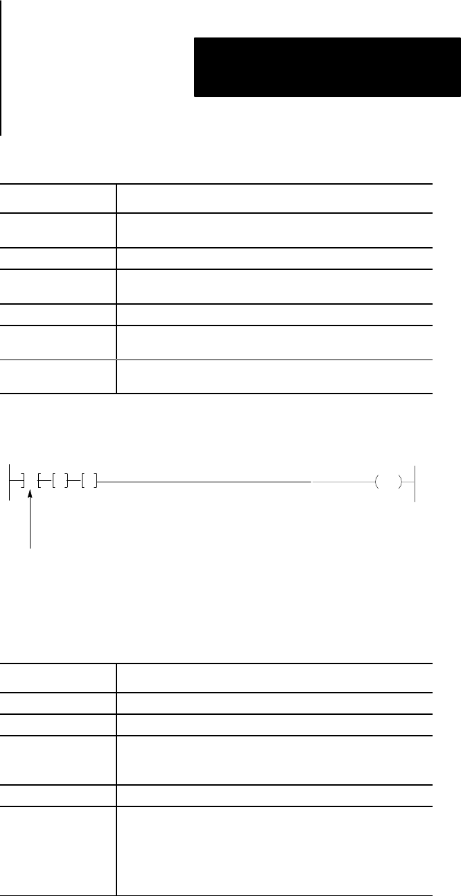
Here is an explanation of each value:
This Value: Stores the:
Data Address First possible address in the timer/counter accumulated value area
of the data table
Module Address RGS for R = rack, G = module, S = slot number
Block Length Number of words to be transferred
Enter 00 for default value or for 64 words
File Address of the first word of the file
Enable bit (EN) Automatically entered from the module address
Set on when the rung containing the instruction is true
Done bit (DN) Automatically entered from the module address
Remains on for 1 program scan following successful transfer
Two GET Method
WYZ
RGS
G
0RGST
Conditions
G
XYZ
ABC
(optional)
10410-I
Here is an explanation of the optional conditions:
This Condition: Examine the:
WYZ First timer/counter address (accumulated area).
XYZ Timer/counter address 100
8
higher than WYZ (preset area).
RGS Location of the block transfer module (I/O rack, module group. and
module slot. S is a zero for the left slot and a 1 for the right slot.
For a 2slot module, S is always zero.
ABC Starting address where data in transferred to/from.
0RGST Output energize initiates Block Transfer.
0 = output byte
R = rack
G = module group
S = module slot
T = 6 for write operation; 7 for read operation