
User Manual Owner's manual
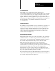
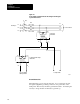
Table Of Contents
- 1772-6.5.8, Mini-PLC-2/02, -2/16, -2/17 Processor, User Manual
- Important User Information
- Summary of Changes
- Table of Contents
- 1 - Using This Manual
- 2 - Fundamentals of a Programmable Controller
- 3 - Hardware Features
- 4 - Installing Your Programmable Controller
- 5 - Starting Your Processor
- 6 - Maintaining and Troubleshooting Your Processor
- 7 - Memory Organization
- 8 - Scan Theory
- 9 - Relay-Like Instructions
- 10 - Program Control Instructions
- 11 - Timers and Counters
- 12 - Data Manipulation and Compare Instructions
- 13 - Three-Digit Math Instructions
- 14 - EAF Math Instructions
- 15 - EAF Log, Trig, and FIFO Instructions
- 16 - EAF Process Control Instructions
- 17 - Jump Instructions and Subroutines
- 18 - Block Transfer
- 19 - Data Transfer Instructions
- 20 - Bit Shift Registers
- 21 - Sequencers
- 22 - Selectable Timer Interrupts
- 23 - Report Generation
- 24 - Program Editing
- 25 - Programming Techniques
- 26 - Program Troubleshooting
- A - Specifications
- B - Processor Comparison Chart
- C - Number Systems
- D - Glossary
- E - Quick Reference
- Index
- Back Cover

Installing Your
Programmable Controller
Chapter 4
4-3
Mechanical
Protection
You provide the enclosure for your processor system. This enclosure is the
primary means of protecting your processor system from atmospheric
contaminants such as oil, moisture, dust, corrosive materials, or other
harmful substances. We suggest that you use an enclosure that conforms to
the National Electrical Manufacturer’s Association standard (NEMA
Standard Publication No. ICS 6).
Mount the enclosure in a position that lets you fully open the doors. You
need easy access to the processor’s wiring and related components.
When choosing the enclosure size, allow extra space for isolation
transformers, fusing, disconnect switch, master control relay and terminal
strips. Your processor requires a minimum of eight inches of space from
the rear of the chassis to the innermost front surface of the enclosure.
Conductor
Categories
When planning your raceway layout, classify into the following categories
all wires and cables connecting your processor system. See the
documentation for each specific I/O module for its individual
classification.
Category-1 Conductors
Category-1 conductors are, in general, high-power conductors that are,
therefore, more tolerant of electrical noise than category 2 conductors and
may also generate more noise. They include:
ac power lines
high-power ac I/O lines — They connect to ac I/O modules that are
rated for high power and high noise immunity.
high-power dc I/O lines — They connect to dc I/O modules that are
rated for high power or have input circuits with long time-constant
filters for high noise rejection. They typically connect to devices
such as:
- hard-contact switches
- relays
- solenoids