
User Manual Owner's manual
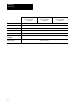
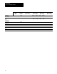
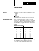
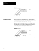
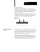
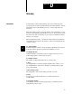
Table Of Contents
- 1772-6.5.8, Mini-PLC-2/02, -2/16, -2/17 Processor, User Manual
- Important User Information
- Summary of Changes
- Table of Contents
- 1 - Using This Manual
- 2 - Fundamentals of a Programmable Controller
- 3 - Hardware Features
- 4 - Installing Your Programmable Controller
- 5 - Starting Your Processor
- 6 - Maintaining and Troubleshooting Your Processor
- 7 - Memory Organization
- 8 - Scan Theory
- 9 - Relay-Like Instructions
- 10 - Program Control Instructions
- 11 - Timers and Counters
- 12 - Data Manipulation and Compare Instructions
- 13 - Three-Digit Math Instructions
- 14 - EAF Math Instructions
- 15 - EAF Log, Trig, and FIFO Instructions
- 16 - EAF Process Control Instructions
- 17 - Jump Instructions and Subroutines
- 18 - Block Transfer
- 19 - Data Transfer Instructions
- 20 - Bit Shift Registers
- 21 - Sequencers
- 22 - Selectable Timer Interrupts
- 23 - Report Generation
- 24 - Program Editing
- 25 - Programming Techniques
- 26 - Program Troubleshooting
- A - Specifications
- B - Processor Comparison Chart
- C - Number Systems
- D - Glossary
- E - Quick Reference
- Index
- Back Cover

Number Systems
Appendix C
C-2
Figure C.1
Decimal
Numbering System
2
3
9
2 x 10
1
= 200
10
3 x 10
1
= 30
10
9 x 10
0
= 9
10
200
30
9
239
10
10
10404-I
Byte word values use the octal numbering system. This is a numbering
system made up eight digits: the numbers 0 through 7 (Table C.A). All
octal numbers are composed of theses digits. The value of an octal number
depends on the digits used and the place value of each digit.
Each place value in an octal number represents a power of eight starting
with eight raised to the zero power (8
0
=1) (Figure C.2). You can compute
the decimal value of an octal number by multiplying each octal digit by its
corresponding place value and adding these numbers together.
Figure C.2
Octal
Numbering System
3
5
7
3 x 8
2
= 192
5 x 8
1
= 40
7 x 7
0
= 7
192
40
7
239
10
8
10404-I
239
10
= 357
8
Octal Numbering System