
User Manual Owner's manual
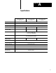
Table Of Contents
- 1772-6.5.8, Mini-PLC-2/02, -2/16, -2/17 Processor, User Manual
- Important User Information
- Summary of Changes
- Table of Contents
- 1 - Using This Manual
- 2 - Fundamentals of a Programmable Controller
- 3 - Hardware Features
- 4 - Installing Your Programmable Controller
- 5 - Starting Your Processor
- 6 - Maintaining and Troubleshooting Your Processor
- 7 - Memory Organization
- 8 - Scan Theory
- 9 - Relay-Like Instructions
- 10 - Program Control Instructions
- 11 - Timers and Counters
- 12 - Data Manipulation and Compare Instructions
- 13 - Three-Digit Math Instructions
- 14 - EAF Math Instructions
- 15 - EAF Log, Trig, and FIFO Instructions
- 16 - EAF Process Control Instructions
- 17 - Jump Instructions and Subroutines
- 18 - Block Transfer
- 19 - Data Transfer Instructions
- 20 - Bit Shift Registers
- 21 - Sequencers
- 22 - Selectable Timer Interrupts
- 23 - Report Generation
- 24 - Program Editing
- 25 - Programming Techniques
- 26 - Program Troubleshooting
- A - Specifications
- B - Processor Comparison Chart
- C - Number Systems
- D - Glossary
- E - Quick Reference
- Index
- Back Cover

Program Troubleshooting
Chapter 26
26-6
Using
a Force Function
You can use force functions in either of two ways using:
bit manipulation/monitor display of an I/O word
ladder diagram display of user program
By pressing [Search] [5] [3] <address>, the bit status and force status of
the 16 corresponding input bits or output terminals of the desired word is
displayed. use the [→] and [←] keys to cursor to the desired bit. Or, in the
ladder diagram display, you can apply forcing by placing the cursor on an
examine or energize instruction. In either case, after you position the
cursor, you can use any one of the following key sequences for placing or
removing a forced condition:
[Force On][Insert]
[Force Off][Insert]
[Force On][Remove]
[Force Off][Remove]
Removing
a Force Function
You can remove all force on or all force off functions at once in ladder
diagram display by pressing either of the following key sequences:
[Force On][Clear Memory]
[Force Off][Clear Memory]
The on/off status of a forced bit appears beneath the bit instruction in
the rung.
In all operating modes, the Industrial Terminal displays a FORCED I/O
message near the bottom of the screen when the processor forces the bits
on or off. In every mode except the Program mode, the Industrial Terminal
displays forced status “on” or “off” below each forced instruction.
Important: The industrial terminal displays the on/off status of
Latch/Unlatch instructions below the instruction. However, the industrial
terminal displays the status of Latch/Unlatch bits only in the
Program/Remote Program mode.
All force functions are cleared when:
you disconnect the industrial terminal from the processor
the processor or industrial terminal loses ac power
you press [Mode Select]