
User Manual Owner's manual
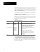
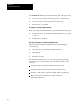
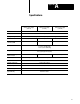
Table Of Contents
- 1772-6.5.8, Mini-PLC-2/02, -2/16, -2/17 Processor, User Manual
- Important User Information
- Summary of Changes
- Table of Contents
- 1 - Using This Manual
- 2 - Fundamentals of a Programmable Controller
- 3 - Hardware Features
- 4 - Installing Your Programmable Controller
- 5 - Starting Your Processor
- 6 - Maintaining and Troubleshooting Your Processor
- 7 - Memory Organization
- 8 - Scan Theory
- 9 - Relay-Like Instructions
- 10 - Program Control Instructions
- 11 - Timers and Counters
- 12 - Data Manipulation and Compare Instructions
- 13 - Three-Digit Math Instructions
- 14 - EAF Math Instructions
- 15 - EAF Log, Trig, and FIFO Instructions
- 16 - EAF Process Control Instructions
- 17 - Jump Instructions and Subroutines
- 18 - Block Transfer
- 19 - Data Transfer Instructions
- 20 - Bit Shift Registers
- 21 - Sequencers
- 22 - Selectable Timer Interrupts
- 23 - Report Generation
- 24 - Program Editing
- 25 - Programming Techniques
- 26 - Program Troubleshooting
- A - Specifications
- B - Processor Comparison Chart
- C - Number Systems
- D - Glossary
- E - Quick Reference
- Index
- Back Cover

Program Troubleshooting
Chapter 26
26-5
Figure 26.1
Contact
Histogram Display
hr.mn.sec.
OFF or ON 00:00'00.00
ON 00:00:00.00OFF 00:00:00.00ON 00:00:00.00
On Time
Off Time
On Time
If the bit is changing states faster than can be printed or displayed, a buffer
stores these changes. If the buffer becomes full, all monitoring stops and a
BUFFER FULL message is displayed. Subsequent changes in the on/off
status of the device are lost until the histogram function finishes printing
out or displaying the data in the buffer. Then a BUFFER RESET message
is displayed and the histogram function resumes.
The industrial terminal screen can display up to 11 lines of data at one
time. In the continuous mode, the screen automatically displays a new
page of data when the screen is full.
In the paged mode, 11 lines fill the screen and the histogram stops. The
buffer stores the subsequent changes until you press [Display] again. One
page of data stored in the buffer is displayed. To terminate the contact
histogram, press [Cancel Command].
You can use the force functions to selectively force an input bit or output
bit on or off. The processor must be operating in the remote test or
run/program mode.
The force functions determine the on/off status of input bits and output bits
by overriding the I/O scan. You can force an input bit on or off regardless
of the actual state of the corresponding input device. However, forcing an
output terminal causes the corresponding output device to be on or off
regardless of the rung logic or the status of the output image table bit.
When you attempt forcing, the processor I/O scan slows down to do the
forcing. When forcing is terminated, the processor automatically switches
back to the faster I/O scan mode.
When the processors is in the remote test mode, it holds outputs off
regardless of attempts to force them on, even though the output bit
instructions are intensified.
Bits may only be forced in the active input or output image tables. Enter
[Search] [5] [0] to view the number of input/output racks available.
Force Functions