
User Manual Owner's manual
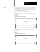
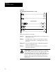
Table Of Contents
- 1772-6.5.8, Mini-PLC-2/02, -2/16, -2/17 Processor, User Manual
- Important User Information
- Summary of Changes
- Table of Contents
- 1 - Using This Manual
- 2 - Fundamentals of a Programmable Controller
- 3 - Hardware Features
- 4 - Installing Your Programmable Controller
- 5 - Starting Your Processor
- 6 - Maintaining and Troubleshooting Your Processor
- 7 - Memory Organization
- 8 - Scan Theory
- 9 - Relay-Like Instructions
- 10 - Program Control Instructions
- 11 - Timers and Counters
- 12 - Data Manipulation and Compare Instructions
- 13 - Three-Digit Math Instructions
- 14 - EAF Math Instructions
- 15 - EAF Log, Trig, and FIFO Instructions
- 16 - EAF Process Control Instructions
- 17 - Jump Instructions and Subroutines
- 18 - Block Transfer
- 19 - Data Transfer Instructions
- 20 - Bit Shift Registers
- 21 - Sequencers
- 22 - Selectable Timer Interrupts
- 23 - Report Generation
- 24 - Program Editing
- 25 - Programming Techniques
- 26 - Program Troubleshooting
- A - Specifications
- B - Processor Comparison Chart
- C - Number Systems
- D - Glossary
- E - Quick Reference
- Index
- Back Cover
Programming Technique
Chapter 25
25-2
When bit 112/04 makes a false-to-true transition, the one-shot bit (bit
253/00) is set on for one scan. The length of time bit 112/04 remains on
and does not affect the one-shot bit due to the next two rungs. Bit 011/14
is latched when bit 112/04 is set or bit 011/14 is unlatched when 112/04 is
reset. Bit 010/00 is then energized because the one-shot bit (bit 253/00) is
set for that scan.
During the next scan, either set of conditions prevents bit 253/00 from
being set. The one-shot bit is set for another scan only when bit 112/04
makes a true-to-false and then a false-to-true transition.
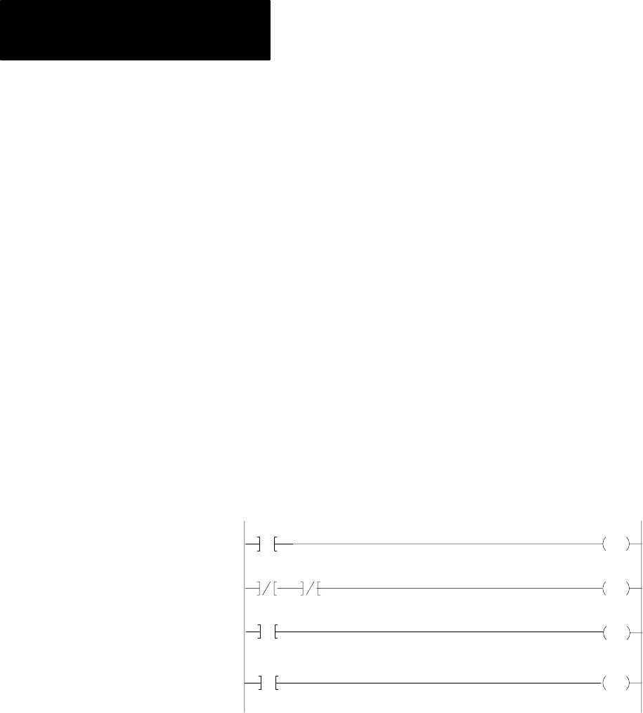
Trailing Edge One Shot
A trailing edge one-shot sets a bit for one scan when its input condition has
made a true-to-false transition. The true-to-false transition represents the
trailing edge of the input pulse. Programming for a trailing edge one-shot
is shown in Figure 25.2.
Figure 25.2
Trailing
Edge One Shot
112
04
253
00
253
00
112
04
253
00
U
011
14
L
011
14
010
00
011
14
When bit 112/04 is set, bit 011/14 is latched. As soon as bit 112/04 makes
a true-to-false transition, the one-shot bit (bit 253/00) is set and bit 011/14
is unlatched. Bit 253/00 remains on for only one scan and energizes
bit 010/00.
The one-shot bit is set for another scan only when the input bit 112/04
makes a false-to-true transition then a true-to-false transition.