
User Manual Owner's manual
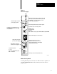
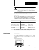
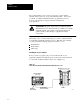
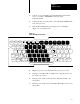
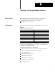
Table Of Contents
- 1772-6.5.8, Mini-PLC-2/02, -2/16, -2/17 Processor, User Manual
- Important User Information
- Summary of Changes
- Table of Contents
- 1 - Using This Manual
- 2 - Fundamentals of a Programmable Controller
- 3 - Hardware Features
- 4 - Installing Your Programmable Controller
- 5 - Starting Your Processor
- 6 - Maintaining and Troubleshooting Your Processor
- 7 - Memory Organization
- 8 - Scan Theory
- 9 - Relay-Like Instructions
- 10 - Program Control Instructions
- 11 - Timers and Counters
- 12 - Data Manipulation and Compare Instructions
- 13 - Three-Digit Math Instructions
- 14 - EAF Math Instructions
- 15 - EAF Log, Trig, and FIFO Instructions
- 16 - EAF Process Control Instructions
- 17 - Jump Instructions and Subroutines
- 18 - Block Transfer
- 19 - Data Transfer Instructions
- 20 - Bit Shift Registers
- 21 - Sequencers
- 22 - Selectable Timer Interrupts
- 23 - Report Generation
- 24 - Program Editing
- 25 - Programming Techniques
- 26 - Program Troubleshooting
- A - Specifications
- B - Processor Comparison Chart
- C - Number Systems
- D - Glossary
- E - Quick Reference
- Index
- Back Cover

Hardware Features
Chapter 3
3-11
Some keys have two symbols occupying one key (Figure 3.5). To display
the top section of each key, press your shift key before the desired symbol.
For example:
To display: 7 A
Press individually: 7 [Shift] A
Data Monitor Functions –– You can display on a CRT and print directly to
a data terminal – binary, hexadecimal, and ASCII data monitor functions
with the keystrokes in Table 21.B.
Data Cartridge Recorder
The data cartridge recorder is a portable recorder that loads programs into
and records the memories of the programmable controllers. Be sure switch
no. 8 of the backplane switch group is OFF (disable memory protect) to
load a program from a cartridge. See the Data Cartridge Recorder User
Manual, publication 1770-6.5.4, for details.
ATTENTION: You must ensure that the addressing mode
stored on the data cartridge and the current addressing mode
selected for the rack are the same prior to uploading a data
cartridge. Failure to do so would result in unpredictable
machine operation. The series C, revision C 1770-T3 terminal
prompts you in choosing the proper addressing mode.
Report Generation Module
The report generation module (cat. no. 1770-RG) provides bi-directional
communication for report generation between the processor and an EIA
RS-232-C peripheral device. The module allows you to store, delete, edit,
report, and display messages in the processor memory.
Power
Supply Modules
The following table lists the power supplies we recommend. If you are
going to parallel a power supply and a 1772-LWP, -LXP, or -LZP
processor, use either a 1771-P3 or 1771-P4 power supply.