
User Manual Owner's manual
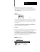
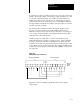
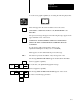
Table Of Contents
- 1772-6.5.8, Mini-PLC-2/02, -2/16, -2/17 Processor, User Manual
- Important User Information
- Summary of Changes
- Table of Contents
- 1 - Using This Manual
- 2 - Fundamentals of a Programmable Controller
- 3 - Hardware Features
- 4 - Installing Your Programmable Controller
- 5 - Starting Your Processor
- 6 - Maintaining and Troubleshooting Your Processor
- 7 - Memory Organization
- 8 - Scan Theory
- 9 - Relay-Like Instructions
- 10 - Program Control Instructions
- 11 - Timers and Counters
- 12 - Data Manipulation and Compare Instructions
- 13 - Three-Digit Math Instructions
- 14 - EAF Math Instructions
- 15 - EAF Log, Trig, and FIFO Instructions
- 16 - EAF Process Control Instructions
- 17 - Jump Instructions and Subroutines
- 18 - Block Transfer
- 19 - Data Transfer Instructions
- 20 - Bit Shift Registers
- 21 - Sequencers
- 22 - Selectable Timer Interrupts
- 23 - Report Generation
- 24 - Program Editing
- 25 - Programming Techniques
- 26 - Program Troubleshooting
- A - Specifications
- B - Processor Comparison Chart
- C - Number Systems
- D - Glossary
- E - Quick Reference
- Index
- Back Cover
Report Generation
Chapter 23
23-16
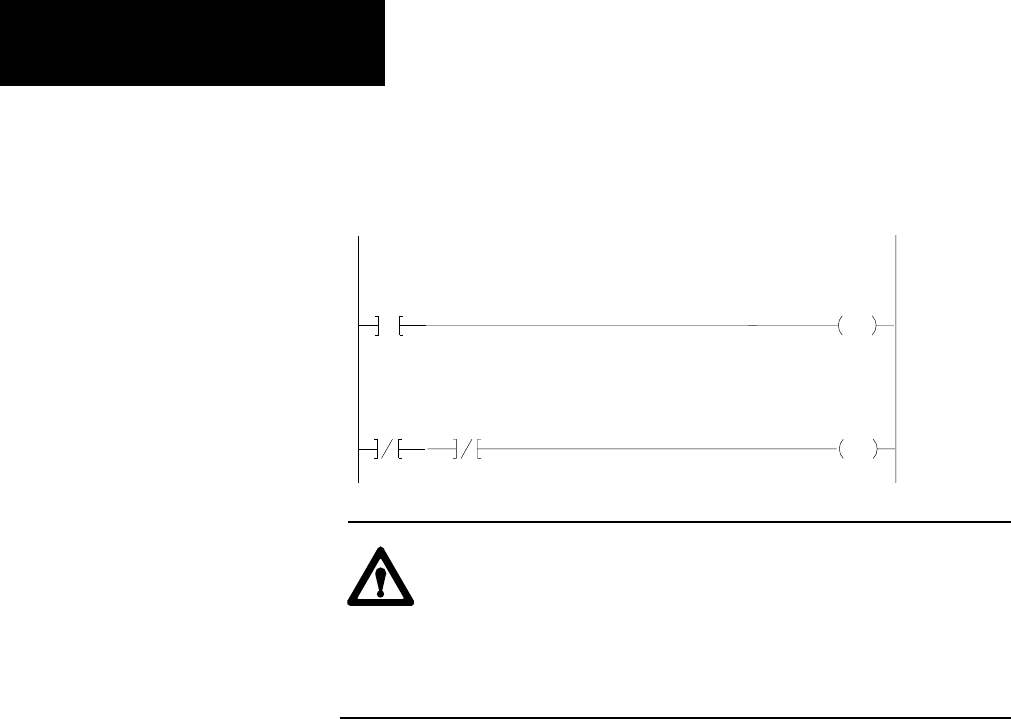
Figure 23.7
Example
Program to Display Any of the Remaining 64 Messages
265
04
L
200
10
Event
Request Bit
Message (010)
RUNG 1
265
04
Event
200
Done Bit
Message (010)
U
200
10
Request Bit
Message (010)
00
RUNG 2
ATTENTION: Do not use message control words for any other
purpose. This warning is especially critical for output image
table locations when output or block transfer modules are
placed in corresponding slots. Failure to observe this warning
could result in hazardous or unexpected machine operation.
This could damage equipment and injure personnel.
The message control word file can be located anywhere in the data table
except in processor work areas and in the input image table. If Memory
Write Protect is active, the message control word file must be placed in the
area of the data table which can be changed (words 010-177).
Several keys and special industrial terminal control codes are used to move
through the display and perform a variety of functions (Table 23.D
and Table 23.E).
Graphic Programming