
User Manual Owner's manual
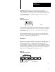
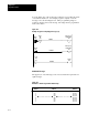
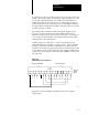
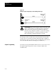
Table Of Contents
- 1772-6.5.8, Mini-PLC-2/02, -2/16, -2/17 Processor, User Manual
- Important User Information
- Summary of Changes
- Table of Contents
- 1 - Using This Manual
- 2 - Fundamentals of a Programmable Controller
- 3 - Hardware Features
- 4 - Installing Your Programmable Controller
- 5 - Starting Your Processor
- 6 - Maintaining and Troubleshooting Your Processor
- 7 - Memory Organization
- 8 - Scan Theory
- 9 - Relay-Like Instructions
- 10 - Program Control Instructions
- 11 - Timers and Counters
- 12 - Data Manipulation and Compare Instructions
- 13 - Three-Digit Math Instructions
- 14 - EAF Math Instructions
- 15 - EAF Log, Trig, and FIFO Instructions
- 16 - EAF Process Control Instructions
- 17 - Jump Instructions and Subroutines
- 18 - Block Transfer
- 19 - Data Transfer Instructions
- 20 - Bit Shift Registers
- 21 - Sequencers
- 22 - Selectable Timer Interrupts
- 23 - Report Generation
- 24 - Program Editing
- 25 - Programming Techniques
- 26 - Program Troubleshooting
- A - Specifications
- B - Processor Comparison Chart
- C - Number Systems
- D - Glossary
- E - Quick Reference
- Index
- Back Cover
Report Generation
Chapter 23
23-15
You define the control word addresses that correspond to the control word
number. The last three digits of the message request bit address are coded
to represent a particular message. For example, message number 312
indicates the 12th bit of the 3rd control word. The message request bit
address (follow the arrows in the figure above) is then 203/12. Likewise,
message number 716 indicates the 16th bit of the 7th control word, with a
message request bit of 207/16.
The message print command is valid for message 0. It prints out the
message control word addresses in a form similar to that shown in
Table 23.A. If the location of the message control file is to be changed or
you no longer need message 0, it can be deleted with the message delete
command and re-entered at any time.
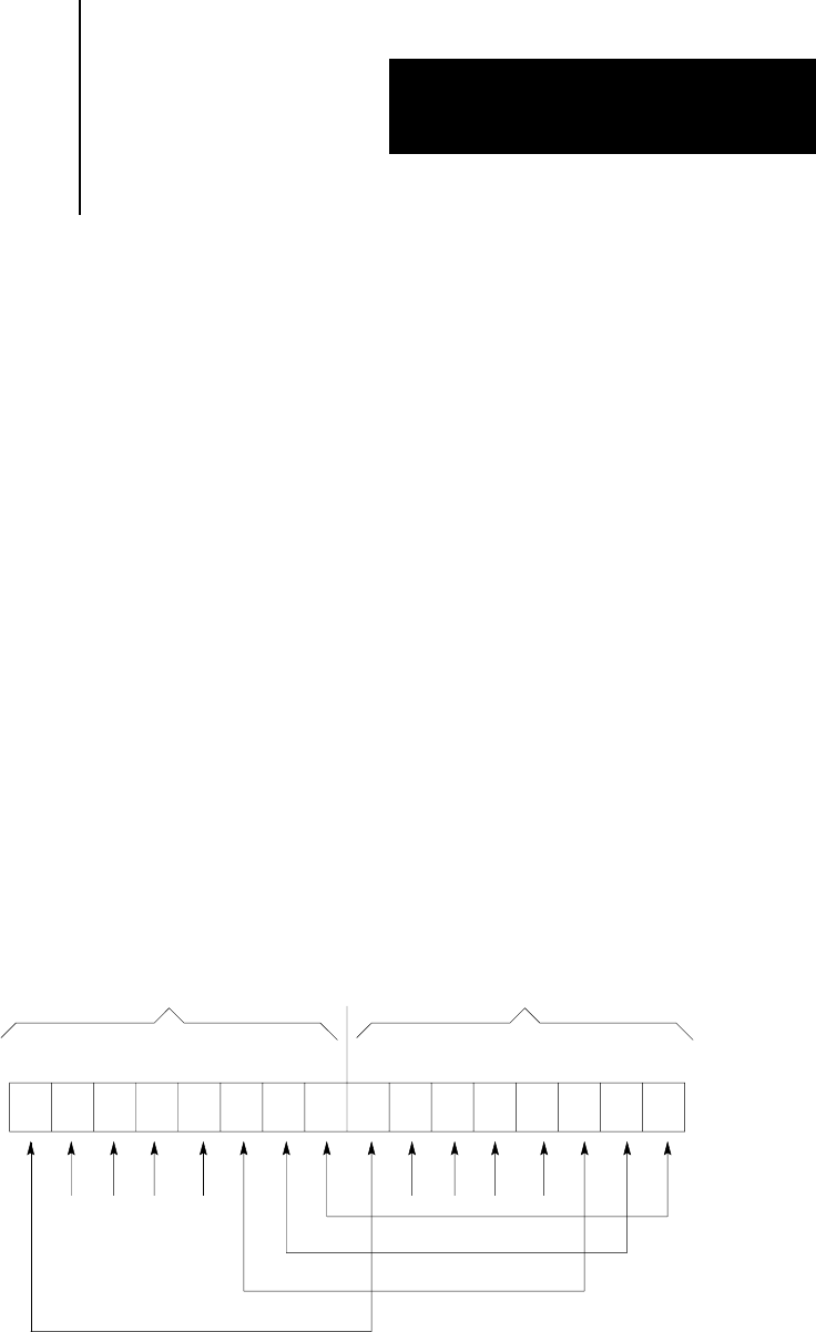
Unlike messages 1-6, which share a common done bit (027/17), the
additional 64 messages each have a separate done bit. After a particular
message is printed, the done bit is set until the user program resets the
request bit. Done bits are located in the lower byte of the message control
words. Figure 23.6 shows this relationship. For example, if 204/15 is the
request bit for a message, the done bit is located at 205/05, one byte below
the request bit.
Figure 23.6
Extended
Message Control W
ord
10401-I
Message Request Bits Message Done Bits
17 10 07 00
Message
Control
Word
Figure 23.7 shows an example program that can be used to display
each message.