
User Manual Owner's manual
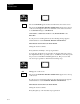
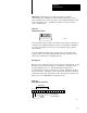
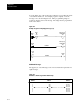
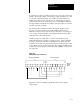
Table Of Contents
- 1772-6.5.8, Mini-PLC-2/02, -2/16, -2/17 Processor, User Manual
- Important User Information
- Summary of Changes
- Table of Contents
- 1 - Using This Manual
- 2 - Fundamentals of a Programmable Controller
- 3 - Hardware Features
- 4 - Installing Your Programmable Controller
- 5 - Starting Your Processor
- 6 - Maintaining and Troubleshooting Your Processor
- 7 - Memory Organization
- 8 - Scan Theory
- 9 - Relay-Like Instructions
- 10 - Program Control Instructions
- 11 - Timers and Counters
- 12 - Data Manipulation and Compare Instructions
- 13 - Three-Digit Math Instructions
- 14 - EAF Math Instructions
- 15 - EAF Log, Trig, and FIFO Instructions
- 16 - EAF Process Control Instructions
- 17 - Jump Instructions and Subroutines
- 18 - Block Transfer
- 19 - Data Transfer Instructions
- 20 - Bit Shift Registers
- 21 - Sequencers
- 22 - Selectable Timer Interrupts
- 23 - Report Generation
- 24 - Program Editing
- 25 - Programming Techniques
- 26 - Program Troubleshooting
- A - Specifications
- B - Processor Comparison Chart
- C - Number Systems
- D - Glossary
- E - Quick Reference
- Index
- Back Cover
Report Generation
Chapter 23
23-14
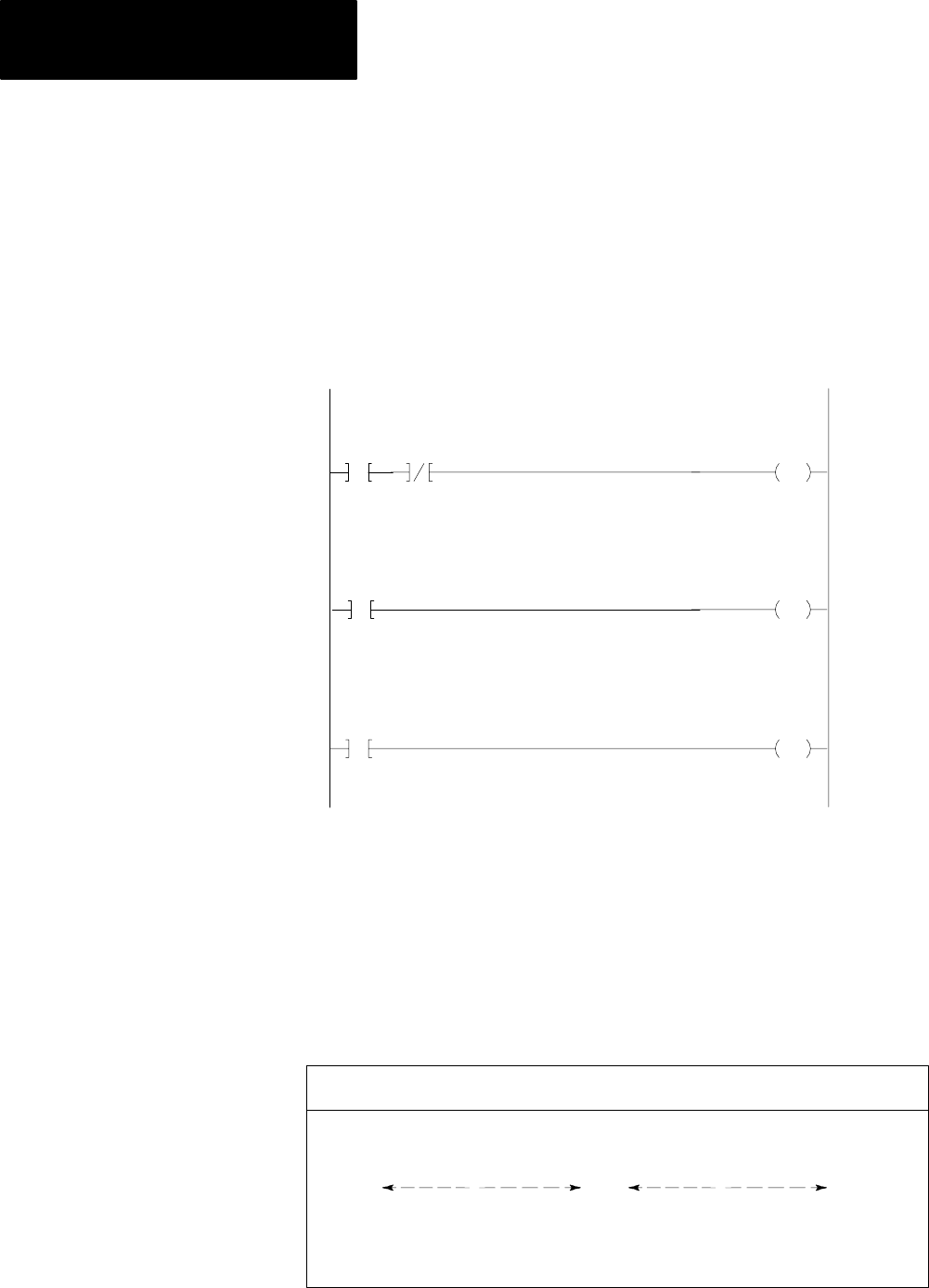
You can display any of the six messages when the corresponding bit 10-15
of word 027 is latched on. An example program to display one of the
messages 1-6 is shown in Figure 23.4. Three programming rungs are
required to display each stored message. The rungs must be programmed
in the order shown.
Figure 23.4
Example
Program For Displaying Messages (16)
265
04
L
027
10
027
16
Event Bit
Busy
Request Bit
Message (1)
Bit
Storage
U
027
10
Request Bit
Message (1)
Bit
Storage
027
Bit
Done
17
RUNG 1
RUNG 2
RUNG 3
Additional
Messages
The upper byte of each message control word contains the request bits for
eight messages.
Figure 23.5
Bit
Address and Message Number Relationship
0
1
2
3
4
5
6
7
201 010-017
110-117
210-217
310-317
410-417
510-517
610-617
710-717
202
203
204
205
206
207
210
Control Word Control Word Message
NumbersAddressNumber