
User Manual Owner's manual
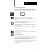
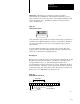
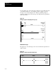
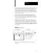
Table Of Contents
- 1772-6.5.8, Mini-PLC-2/02, -2/16, -2/17 Processor, User Manual
- Important User Information
- Summary of Changes
- Table of Contents
- 1 - Using This Manual
- 2 - Fundamentals of a Programmable Controller
- 3 - Hardware Features
- 4 - Installing Your Programmable Controller
- 5 - Starting Your Processor
- 6 - Maintaining and Troubleshooting Your Processor
- 7 - Memory Organization
- 8 - Scan Theory
- 9 - Relay-Like Instructions
- 10 - Program Control Instructions
- 11 - Timers and Counters
- 12 - Data Manipulation and Compare Instructions
- 13 - Three-Digit Math Instructions
- 14 - EAF Math Instructions
- 15 - EAF Log, Trig, and FIFO Instructions
- 16 - EAF Process Control Instructions
- 17 - Jump Instructions and Subroutines
- 18 - Block Transfer
- 19 - Data Transfer Instructions
- 20 - Bit Shift Registers
- 21 - Sequencers
- 22 - Selectable Timer Interrupts
- 23 - Report Generation
- 24 - Program Editing
- 25 - Programming Techniques
- 26 - Program Troubleshooting
- A - Specifications
- B - Processor Comparison Chart
- C - Number Systems
- D - Glossary
- E - Quick Reference
- Index
- Back Cover
Report Generation
Chapter 23
23-13
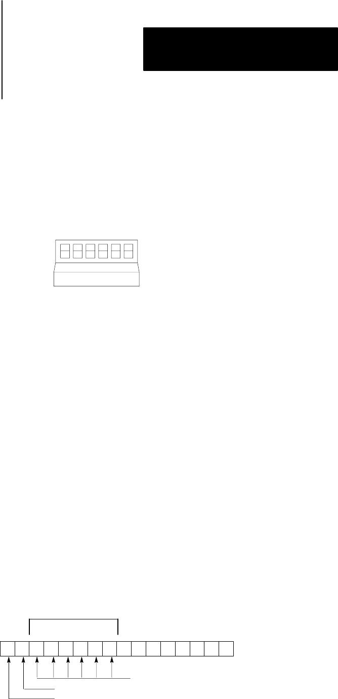
Important: Automatic report generation can also be activated
automatically upon initialization of the industrial terminal if you move
parity switches 4 and 5 to the up position on the industrial terminal’s main
logic board (Figure 23.2). To find these switches, turn power off and
remove the keyboard.
Figure 23.2
Parity
Switch Locations
1234 56
10664I
Once automatic report generation is activated, the message request bits are
scanned by the industrial terminal for a false-to-true transition. Each time
one of the request bits goes true, the corresponding message is printed
automatically.
You can terminate automatic report generation by pressing [Esc]. The
display returns to the ladder diagram if automatic report generation was
entered by a command from a peripheral device.
Messages
16
Bits 10-15 of word 027 are used to control messages 1-6 (Figure 23.3). Bit
027/10 is the request message number 1, bit 027/11 is the request bit for
message number 2 and so on. The remaining 64 messages have a
user-defined file of message request bits for control. Bit 027/16, the busy
bit is set when any of messages 1-6 are requested and remains set until all
requested messages have been printed. Once all messages are printed, bit
027/17 stays on for 300 milliseconds and then resets.
Figure 23.3
Bit
Assignments in Word 027
17 16 15 14 13 12 11 10 07 00
(6)
(5) (4) (3) (2) (1)
Busy BIt
Done Bit
Corresponding
Message Numbers
Request Bits
10399-I