
User Manual Owner's manual
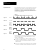
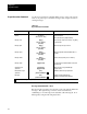
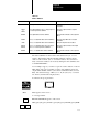

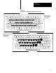
Table Of Contents
- 1772-6.5.8, Mini-PLC-2/02, -2/16, -2/17 Processor, User Manual
- Important User Information
- Summary of Changes
- Table of Contents
- 1 - Using This Manual
- 2 - Fundamentals of a Programmable Controller
- 3 - Hardware Features
- 4 - Installing Your Programmable Controller
- 5 - Starting Your Processor
- 6 - Maintaining and Troubleshooting Your Processor
- 7 - Memory Organization
- 8 - Scan Theory
- 9 - Relay-Like Instructions
- 10 - Program Control Instructions
- 11 - Timers and Counters
- 12 - Data Manipulation and Compare Instructions
- 13 - Three-Digit Math Instructions
- 14 - EAF Math Instructions
- 15 - EAF Log, Trig, and FIFO Instructions
- 16 - EAF Process Control Instructions
- 17 - Jump Instructions and Subroutines
- 18 - Block Transfer
- 19 - Data Transfer Instructions
- 20 - Bit Shift Registers
- 21 - Sequencers
- 22 - Selectable Timer Interrupts
- 23 - Report Generation
- 24 - Program Editing
- 25 - Programming Techniques
- 26 - Program Troubleshooting
- A - Specifications
- B - Processor Comparison Chart
- C - Number Systems
- D - Glossary
- E - Quick Reference
- Index
- Back Cover

MS,n
RETURN
ESC ESC
Report Generation
Chapter 23
23-5
Table 23.C
Address Delimiters
Delimiter Format Explanation Message Report Format
*XXX* Enter 3digit word address between delimiters. Displays the 3digit BCD value at assigned
word address.
*XXX1*
or
*XXX0*
Enter 3digit word address and a 1" for upper byte or a
0" for lower byte between delimiters.
Displays the 3digit octal value at assigned
byte address.
*XXXXX* Enter 5digit bit address between delimiters. Displays the On or Off status of the assigned bit
address.
#XXX# Enter 3, 4, or 5digit word address between delimiters. Displays the 3digit BCD value at assigned
word address.
!XXX! Enter 3, 4, or 5digit word address between delimiters. Displays the 4digit hex value at address.
&XXX1&
&XXX0&
Enter 3, 4, or 5 digit word address and a 1"for upper
byte or a 0" for lower byte between delimiters.
Displays the 3digit octal value at the assigned
byte address.
^XXXXX^ Enter 5, 6, or 7digit bit address between delimiters. Displays the On or Off status of the assigned bit
address.
The desired delimiter is entered before and after the bit, byte, or word
address. The delimiter tells the industrial terminal to print the current
status or value of the bit, byte, or word at the address. You can enter as
many consecutive addresses as needed by sharing the same delimiter, such
as *XXX*XXX*XXX*.
As an example, suppose you want to report the on/off condition of a device
SR6, during each cycle of machine operation. The delimiters denote the
output address 013/05, and the cycle counter accumulated value (stored at
030). The desired message, “SR6 is (on or off) in cycle (xxx)”, is entered
into memory with the following keystrokes:
You must be in report generation.
MS,n appears on the screen.
n = message number
READY FOR INPUT appears on the screen.
SR6 [space] IS [space] *01305* [space] IN [space] CYCLE [space] #030#