
User Manual Owner's manual
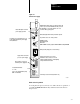
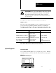
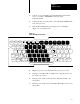
Table Of Contents
- 1772-6.5.8, Mini-PLC-2/02, -2/16, -2/17 Processor, User Manual
- Important User Information
- Summary of Changes
- Table of Contents
- 1 - Using This Manual
- 2 - Fundamentals of a Programmable Controller
- 3 - Hardware Features
- 4 - Installing Your Programmable Controller
- 5 - Starting Your Processor
- 6 - Maintaining and Troubleshooting Your Processor
- 7 - Memory Organization
- 8 - Scan Theory
- 9 - Relay-Like Instructions
- 10 - Program Control Instructions
- 11 - Timers and Counters
- 12 - Data Manipulation and Compare Instructions
- 13 - Three-Digit Math Instructions
- 14 - EAF Math Instructions
- 15 - EAF Log, Trig, and FIFO Instructions
- 16 - EAF Process Control Instructions
- 17 - Jump Instructions and Subroutines
- 18 - Block Transfer
- 19 - Data Transfer Instructions
- 20 - Bit Shift Registers
- 21 - Sequencers
- 22 - Selectable Timer Interrupts
- 23 - Report Generation
- 24 - Program Editing
- 25 - Programming Techniques
- 26 - Program Troubleshooting
- A - Specifications
- B - Processor Comparison Chart
- C - Number Systems
- D - Glossary
- E - Quick Reference
- Index
- Back Cover
Hardware Features
Chapter 3
3-9
1. Connect one end of the PLC-2 Program Panel Interconnect Cable
(cat. no. 1772-TC) to CHANNEL A at the rear of the
industrial terminal.
2. Connect the other end of the cable to the socket labeled INTFC at the
front of the processor.
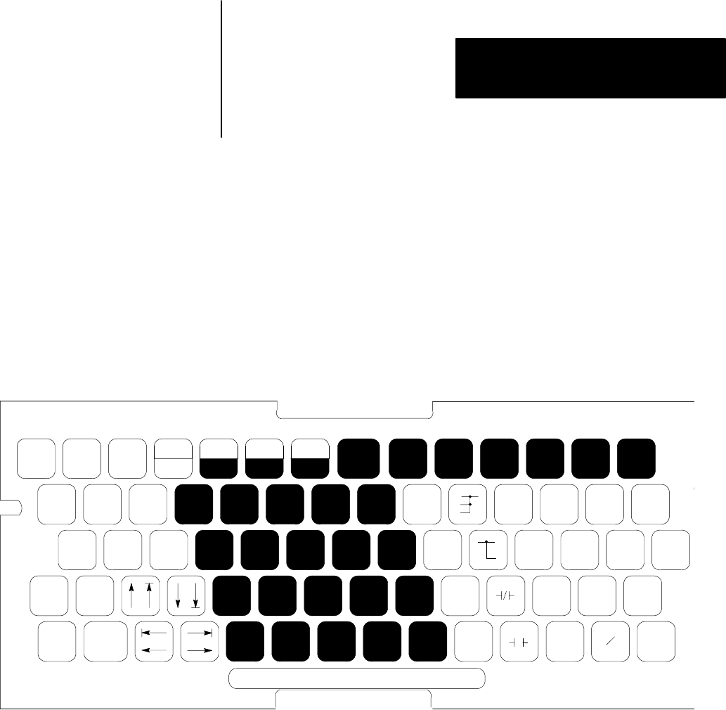
3. Place the PLC-2 Family Keytop Overlay (cat. no. 1770-KFA)
(Figure 3.5) onto the keyboard.
Figure 3.5
A
PLC2 Family Keytop Overlay
MODE
SELECT
DATA
INIT
EXPAND
ADDR
SBR
T.END
-(RET)-
-(JSR)-
LBL
-(JMP)-
EAF
-(SCT)-
CONVERT FILE SEQ
SHIFT
REG
BLOCK
X-FER
RECORD
RUNG SEARCH
-(
÷ )-
-[ G ]-
-[ I ]-
-(CTU)- -(TON)-
-( L
)-
A
7
B
8
C
9
DISPLAY INSERT REMOVE
-( X )-
-[ = ]-
-[ L
]-
-(CTD)- -(TOF)-
-( U )-
D
4
E
5
F
6
HELP
SHIFT
CLEAR
MEMORY
CANCEL
COMMAND
-( – )-
-[ < ]-
-[ B ]-
-(CTR)- -(RTO)- -(MCR)-
123
-( + )-
-(PUT)- -(IOT)- -(ZCL)- -(RTR)-
-( )-
FORCE
OFF
FORCE
ON
0
4. Plug the ac power cord of the terminal into the ac power source.
5. If using a 1772-LWP, -LXP, or -LZP processor, plug the power cord
into the ac power source.
6. Turn the power switch on the front of the industrial terminal to the
ON position.
7. Turn the power switch of the 1772-LWP, -LXP, -LZP processor to the
ON position.