
User Manual Owner's manual
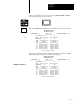
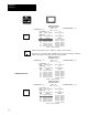
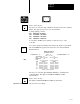
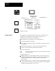
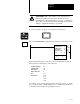
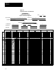
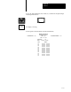
Table Of Contents
- 1772-6.5.8, Mini-PLC-2/02, -2/16, -2/17 Processor, User Manual
- Important User Information
- Summary of Changes
- Table of Contents
- 1 - Using This Manual
- 2 - Fundamentals of a Programmable Controller
- 3 - Hardware Features
- 4 - Installing Your Programmable Controller
- 5 - Starting Your Processor
- 6 - Maintaining and Troubleshooting Your Processor
- 7 - Memory Organization
- 8 - Scan Theory
- 9 - Relay-Like Instructions
- 10 - Program Control Instructions
- 11 - Timers and Counters
- 12 - Data Manipulation and Compare Instructions
- 13 - Three-Digit Math Instructions
- 14 - EAF Math Instructions
- 15 - EAF Log, Trig, and FIFO Instructions
- 16 - EAF Process Control Instructions
- 17 - Jump Instructions and Subroutines
- 18 - Block Transfer
- 19 - Data Transfer Instructions
- 20 - Bit Shift Registers
- 21 - Sequencers
- 22 - Selectable Timer Interrupts
- 23 - Report Generation
- 24 - Program Editing
- 25 - Programming Techniques
- 26 - Program Troubleshooting
- A - Specifications
- B - Processor Comparison Chart
- C - Number Systems
- D - Glossary
- E - Quick Reference
- Index
- Back Cover
SEQ
Sequencer
Chapter 21
21-21
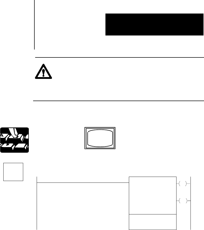
ATTENTION: The counter address of the sequencer load
instruction should be reserved for that instruction. Do not
manipulate the counter accumulated or preset word. Changes to
these values could result in unexpected machine operation with
damage to equipment and injury to personnel.
You are now ready to program your sequencer load instruction.
The word SEQUENCER is displayed in the lower left corner of the screen.
SEQUENCER INPUT
COUNTER ADDR:
CURRENT STEP:
SEQ LENGTH:
WORDS PER STEP:
FILE:
001
1
110
INPUT WORDS
2:
3: 4:
030
001
110-
1:010
EN
DN
17
15
030
030
2
Insert the following values. The cursor moves automatically throughout
the Sequencer Load instruction. The values are:
COUNTER ADDRESS 056
CURRENT STEP 008
SEQ LENGTH 012
WORDS PER STEP 4
FILE 510
LOAD WORDS 1: 110
2: 113
3: 012
4: 314
To continue, enter your data using the binary data monitor mode. You will
get your data from the worksheet (Figure 21.7). A filled-in block means a
1 should be inserted in the corresponding bit location.