
User Manual Owner's manual
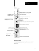
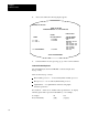
Table Of Contents
- 1772-6.5.8, Mini-PLC-2/02, -2/16, -2/17 Processor, User Manual
- Important User Information
- Summary of Changes
- Table of Contents
- 1 - Using This Manual
- 2 - Fundamentals of a Programmable Controller
- 3 - Hardware Features
- 4 - Installing Your Programmable Controller
- 5 - Starting Your Processor
- 6 - Maintaining and Troubleshooting Your Processor
- 7 - Memory Organization
- 8 - Scan Theory
- 9 - Relay-Like Instructions
- 10 - Program Control Instructions
- 11 - Timers and Counters
- 12 - Data Manipulation and Compare Instructions
- 13 - Three-Digit Math Instructions
- 14 - EAF Math Instructions
- 15 - EAF Log, Trig, and FIFO Instructions
- 16 - EAF Process Control Instructions
- 17 - Jump Instructions and Subroutines
- 18 - Block Transfer
- 19 - Data Transfer Instructions
- 20 - Bit Shift Registers
- 21 - Sequencers
- 22 - Selectable Timer Interrupts
- 23 - Report Generation
- 24 - Program Editing
- 25 - Programming Techniques
- 26 - Program Troubleshooting
- A - Specifications
- B - Processor Comparison Chart
- C - Number Systems
- D - Glossary
- E - Quick Reference
- Index
- Back Cover
Hardware Features
Chapter 3
3-8
We recommend that you use a series C, revision C or later 1770-T3
terminal; earlier versions do not provide full functionality. You can use
a 1770-T1 or 1770-T2 industrial terminal to program the processors;
however, only instructions supported by these terminals can
be programmed.
ATTENTION: Programs entered using a 1770-T3 Industrial
Terminal must not be edited with either a 1770-T1 or a 1770-T2
industrial terminal. Such editing could result in unexpected
operation with possible damage to equipment and injury
to personnel.
When using 1-slot or 1/2-slot addressing, use a series C 1770-T3 terminal
to obtain full compatibility with the processor. With this series terminal,
you can perform the following operations in rack 1, 2, 3 or 4.
immediate I/O
block transfer
full forcing
Installing
the 1770T3 T
erminal
Before you start to program your processor make sure all of your
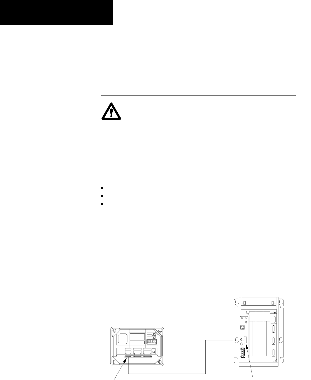
peripheral equipment is installed properly. Follow these basic instructions
to connect the 1770-T3 terminal to the processor (Figure 3.4).
Figure 3.4
The
Connections Between an Industrial T
erminal and a Processor
Channel A
Industrial Terminal
(rear view)
Program Panel
Interconnect Cable
Interface
MiniPLC2/02, 2/16, 2/17
PLC2 Family
10249