
User Manual Owner's manual
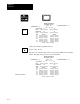
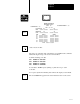
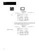
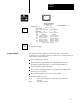
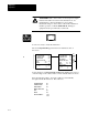
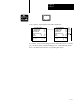
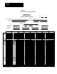
Table Of Contents
- 1772-6.5.8, Mini-PLC-2/02, -2/16, -2/17 Processor, User Manual
- Important User Information
- Summary of Changes
- Table of Contents
- 1 - Using This Manual
- 2 - Fundamentals of a Programmable Controller
- 3 - Hardware Features
- 4 - Installing Your Programmable Controller
- 5 - Starting Your Processor
- 6 - Maintaining and Troubleshooting Your Processor
- 7 - Memory Organization
- 8 - Scan Theory
- 9 - Relay-Like Instructions
- 10 - Program Control Instructions
- 11 - Timers and Counters
- 12 - Data Manipulation and Compare Instructions
- 13 - Three-Digit Math Instructions
- 14 - EAF Math Instructions
- 15 - EAF Log, Trig, and FIFO Instructions
- 16 - EAF Process Control Instructions
- 17 - Jump Instructions and Subroutines
- 18 - Block Transfer
- 19 - Data Transfer Instructions
- 20 - Bit Shift Registers
- 21 - Sequencers
- 22 - Selectable Timer Interrupts
- 23 - Report Generation
- 24 - Program Editing
- 25 - Programming Techniques
- 26 - Program Troubleshooting
- A - Specifications
- B - Processor Comparison Chart
- C - Number Systems
- D - Glossary
- E - Quick Reference
- Index
- Back Cover
Sequencer
Chapter 21
21-15
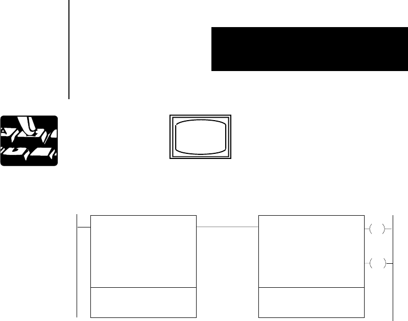
Your sequencer output instruction should look like this:
SEQUENCER INPUT
COUNTER ADDR:
CURRENT STEP:
SEQ LENGTH:
WORDS PER STEP:
FILE:
006
2
413
MASK:
071
INPUT WORDS
2:
3: 4:
200
001
400-
070-
1: 110
201
SEQUENCER INPUT
COUNTER ADDR:
CURRENT STEP:
SEQ LENGTH:
WORDS PER STEP:
FILE:
006
2
613
MASK:
076
INPUT WORDS
2:
3: 4:
200
001
600-
075-
1: 012
013
EN
DN
17
15
200
200
To continue, enter your data using the binary data monitor mode. You will
get your data from the worksheet in Figure 21.6. A filled-in block means
that a 1 should be inserted in the corresponding bit location.