
User Manual Owner's manual
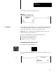
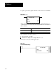
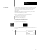
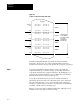
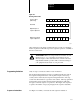
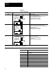
Table Of Contents
- 1772-6.5.8, Mini-PLC-2/02, -2/16, -2/17 Processor, User Manual
- Important User Information
- Summary of Changes
- Table of Contents
- 1 - Using This Manual
- 2 - Fundamentals of a Programmable Controller
- 3 - Hardware Features
- 4 - Installing Your Programmable Controller
- 5 - Starting Your Processor
- 6 - Maintaining and Troubleshooting Your Processor
- 7 - Memory Organization
- 8 - Scan Theory
- 9 - Relay-Like Instructions
- 10 - Program Control Instructions
- 11 - Timers and Counters
- 12 - Data Manipulation and Compare Instructions
- 13 - Three-Digit Math Instructions
- 14 - EAF Math Instructions
- 15 - EAF Log, Trig, and FIFO Instructions
- 16 - EAF Process Control Instructions
- 17 - Jump Instructions and Subroutines
- 18 - Block Transfer
- 19 - Data Transfer Instructions
- 20 - Bit Shift Registers
- 21 - Sequencers
- 22 - Selectable Timer Interrupts
- 23 - Report Generation
- 24 - Program Editing
- 25 - Programming Techniques
- 26 - Program Troubleshooting
- A - Specifications
- B - Processor Comparison Chart
- C - Number Systems
- D - Glossary
- E - Quick Reference
- Index
- Back Cover
592
SEARCH
50
04
Sequencer
Chapter 21
21-5
The Sequencer Input instruction compares all 16 bits of input data to data
stored in its file (data table) for equality. Here are some characteristics of
the sequencer input instruction.
You can compare up to 64 bits.
This instruction is programmed as an input instruction (can be
programmed in the same rung as a sequencer output instruction).
You can mask the unused input bits.
The sequencer input instruction is externally controlled by a counter
instruction with ladder logic in your program.
This instruction requires 5-8 words of your program.
If the rung becomes:
True The instruction increments to the next step and compares the
input word(s) to current step for equality.
False No action is taken.
ATTENTION: The counter address for the Sequencer Output
instruction should be reserved for that instruction. Do not
manipulate the counter accumulated or preset values.
Inadvertent changes to these values could result in hazardous
machine operation or a run time error. Damage to equipment
and/or personal injury could result.
To enter a Sequencer Input instruction, start by expanding your data table
if required. Expand it to a size large enough to store your program.
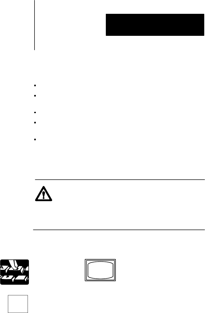
The word SEARCH appears in the lower left corner of the Industrial
Terminal Screen.
Puts the processor in the remote program mode.
The DATA TABLE CONFIGURATION appears. The cursor is on the first
digit of NUMBER OF 128 WORD D. T. BLOCKS.
To be able to use the sequencer input, output ,and load examples, do
the following:
Sequencer Input