
User Manual Owner's manual
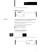
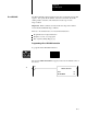
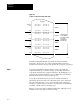
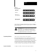
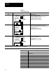
Table Of Contents
- 1772-6.5.8, Mini-PLC-2/02, -2/16, -2/17 Processor, User Manual
- Important User Information
- Summary of Changes
- Table of Contents
- 1 - Using This Manual
- 2 - Fundamentals of a Programmable Controller
- 3 - Hardware Features
- 4 - Installing Your Programmable Controller
- 5 - Starting Your Processor
- 6 - Maintaining and Troubleshooting Your Processor
- 7 - Memory Organization
- 8 - Scan Theory
- 9 - Relay-Like Instructions
- 10 - Program Control Instructions
- 11 - Timers and Counters
- 12 - Data Manipulation and Compare Instructions
- 13 - Three-Digit Math Instructions
- 14 - EAF Math Instructions
- 15 - EAF Log, Trig, and FIFO Instructions
- 16 - EAF Process Control Instructions
- 17 - Jump Instructions and Subroutines
- 18 - Block Transfer
- 19 - Data Transfer Instructions
- 20 - Bit Shift Registers
- 21 - Sequencers
- 22 - Selectable Timer Interrupts
- 23 - Report Generation
- 24 - Program Editing
- 25 - Programming Techniques
- 26 - Program Troubleshooting
- A - Specifications
- B - Processor Comparison Chart
- C - Number Systems
- D - Glossary
- E - Quick Reference
- Index
- Back Cover
Sequencer
Chapter 21
21-3
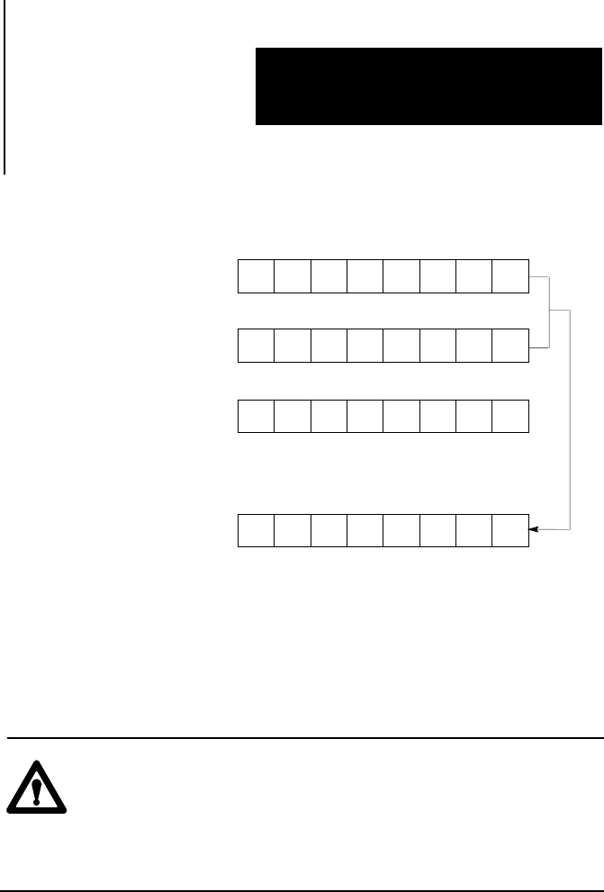
Figure 21.3
Masking
T
ransfer Data
0 1 0 1 1 0 1 0
1 0 0 1 1 0 0 1
1 1 1 0 1 0 0 0
0 1 1 1 1 0 0 0
Sequencer Word
(Current Step)
Mask Word
Output Word prior to
Sequencer Operations
Output word result after
Sequencer Operations
10393-I
Other instructions can change a mask in the user program. If a changing
mask is required for different steps in the sequencer operation, a Get/Put or
file move can be used.
ATTENTION: When choosing a mask word address, be sure
that the next 1, 2, or 3 consecutive word addresses are not
already assigned. Other data written into a mask could cause
unpredictable machine operation. This could cause damage to
your equipment and/or injury to your personnel.
Only one step is executed at a time for each instruction.
The Sequencer Input instruction can be programmed in the same rung as
the Sequencer Output instruction. The sequencer input counter (step
counter) can be indexed by the Sequencer Output instruction. The step
counter in both instructions is given the same address. When programmed
in this manner, the Sequencer Input and Output instructions will track
through a controlled sequence of operations. The length of the sequencer
is equal to the number of steps (Seq Length) in the sequencer data table.
Use Figure 21.4 while you read about each sequencer instruction.
Programming Limitations
Sequencer Instructions