
User Manual Owner's manual
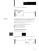
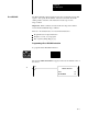
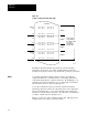
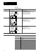
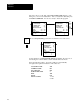
Table Of Contents
- 1772-6.5.8, Mini-PLC-2/02, -2/16, -2/17 Processor, User Manual
- Important User Information
- Summary of Changes
- Table of Contents
- 1 - Using This Manual
- 2 - Fundamentals of a Programmable Controller
- 3 - Hardware Features
- 4 - Installing Your Programmable Controller
- 5 - Starting Your Processor
- 6 - Maintaining and Troubleshooting Your Processor
- 7 - Memory Organization
- 8 - Scan Theory
- 9 - Relay-Like Instructions
- 10 - Program Control Instructions
- 11 - Timers and Counters
- 12 - Data Manipulation and Compare Instructions
- 13 - Three-Digit Math Instructions
- 14 - EAF Math Instructions
- 15 - EAF Log, Trig, and FIFO Instructions
- 16 - EAF Process Control Instructions
- 17 - Jump Instructions and Subroutines
- 18 - Block Transfer
- 19 - Data Transfer Instructions
- 20 - Bit Shift Registers
- 21 - Sequencers
- 22 - Selectable Timer Interrupts
- 23 - Report Generation
- 24 - Program Editing
- 25 - Programming Techniques
- 26 - Program Troubleshooting
- A - Specifications
- B - Processor Comparison Chart
- C - Number Systems
- D - Glossary
- E - Quick Reference
- Index
- Back Cover
Bit Shift Registers
Chapter 20
20-13
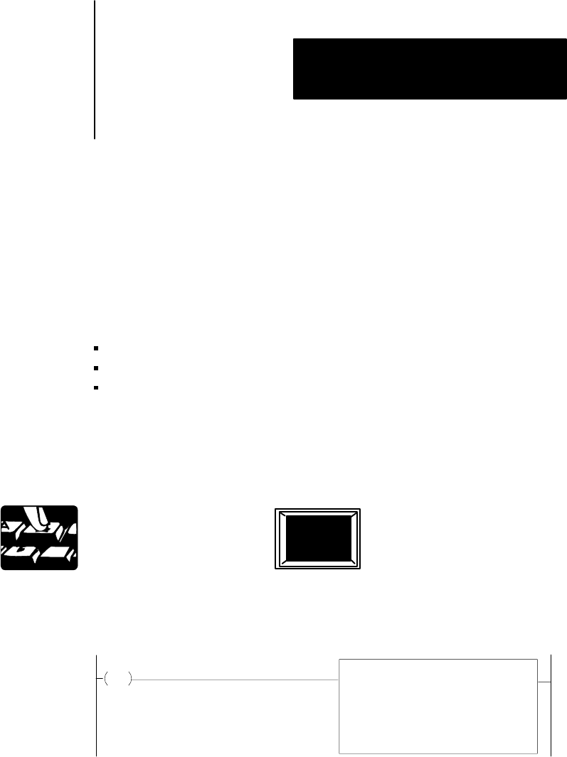
The Reset Shift Bit output instruction turns off a specified bit in a bit shift
register. You specify the bit number of the bit to be turned off and the
starting address of the file. The instruction executes upon a true
rung condition.
Important: If file is shifted, new data in the same bit position will be
reset if the Reset Shift Bit rung is still true.
Here are some characteristics of a reset shift bit instruction:
Programmed as an output instruction
Requires 3 words of your program
Key sequence [Shift] [Reg] [1] [7]
Programming a Reset Bit Shift Instruction
To program a Reset Bit Shift instruction:
The prompt SHIFT REGISTER 12 appears in the lower left hand corner of
the screen.
RESET SHIFT BIT
FILE:
BIT NUMBER: 001
020
10
110
17
Reset Bit Shift