
User Manual Owner's manual
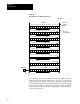
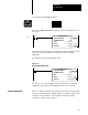
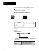
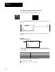
Table Of Contents
- 1772-6.5.8, Mini-PLC-2/02, -2/16, -2/17 Processor, User Manual
- Important User Information
- Summary of Changes
- Table of Contents
- 1 - Using This Manual
- 2 - Fundamentals of a Programmable Controller
- 3 - Hardware Features
- 4 - Installing Your Programmable Controller
- 5 - Starting Your Processor
- 6 - Maintaining and Troubleshooting Your Processor
- 7 - Memory Organization
- 8 - Scan Theory
- 9 - Relay-Like Instructions
- 10 - Program Control Instructions
- 11 - Timers and Counters
- 12 - Data Manipulation and Compare Instructions
- 13 - Three-Digit Math Instructions
- 14 - EAF Math Instructions
- 15 - EAF Log, Trig, and FIFO Instructions
- 16 - EAF Process Control Instructions
- 17 - Jump Instructions and Subroutines
- 18 - Block Transfer
- 19 - Data Transfer Instructions
- 20 - Bit Shift Registers
- 21 - Sequencers
- 22 - Selectable Timer Interrupts
- 23 - Report Generation
- 24 - Program Editing
- 25 - Programming Techniques
- 26 - Program Troubleshooting
- A - Specifications
- B - Processor Comparison Chart
- C - Number Systems
- D - Glossary
- E - Quick Reference
- Index
- Back Cover

Bit Shift Registers
Chapter 20
20-6
Upon false-to-true rung transition, input bit B from a particular input word
will be inserted into the last bit of the bit shift register. In Figure 20.4, bit
128 moves right and displaces bit 127; bit 127 displaces bit 126. Each bit
displaces the one on its right until the first bit in the word, 113, is reached.
Bit 113 then displaces bit 112 in the previous word (in this example, bit
406/17). This bumping procedure continues throughout the queue until bit
1 is ejected from the file into output bit A.
If the bit shift register of Figure 20.4 had been 123 bits long it would have
input data into bit 12 of word 407. In this case the bits to the left of bit 12
in word 407 would be unused and cannot be used for any other purpose. A
Bit Shift Right will shift the on or off status of input bit B directly into bit
123 as shown by the dotted line.
The instruction operates in the complete mode. The status of the input bit
is shifted into the last bit in the register and the status of the first bit in the
register is shifted into the output bit in one scan.
Here are some characteristics of the Bit Shift Right instruction:
Programmed as an output instruction
Key sequence [Shift] [Reg] [1] [3]
The counter is internally indexed and externally controlled by the ladder
diagram logic in your program.
Operates in complete mode
Requires 6 words of your program
Programming Bit Shift Right Instruction
ATTENTION: The counter address specified for the Bit Shift
Right instruction should be reserved for that instruction only.
Do not manipulate the counter preset or accumulated values.
Inadvertent change to these values could result in hazardous or
unpredictable machine operation or a run time error. Damage to
equipment and/or personal injury could result.