
User Manual Owner's manual
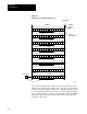
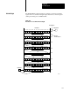
Table Of Contents
- 1772-6.5.8, Mini-PLC-2/02, -2/16, -2/17 Processor, User Manual
- Important User Information
- Summary of Changes
- Table of Contents
- 1 - Using This Manual
- 2 - Fundamentals of a Programmable Controller
- 3 - Hardware Features
- 4 - Installing Your Programmable Controller
- 5 - Starting Your Processor
- 6 - Maintaining and Troubleshooting Your Processor
- 7 - Memory Organization
- 8 - Scan Theory
- 9 - Relay-Like Instructions
- 10 - Program Control Instructions
- 11 - Timers and Counters
- 12 - Data Manipulation and Compare Instructions
- 13 - Three-Digit Math Instructions
- 14 - EAF Math Instructions
- 15 - EAF Log, Trig, and FIFO Instructions
- 16 - EAF Process Control Instructions
- 17 - Jump Instructions and Subroutines
- 18 - Block Transfer
- 19 - Data Transfer Instructions
- 20 - Bit Shift Registers
- 21 - Sequencers
- 22 - Selectable Timer Interrupts
- 23 - Report Generation
- 24 - Program Editing
- 25 - Programming Techniques
- 26 - Program Troubleshooting
- A - Specifications
- B - Processor Comparison Chart
- C - Number Systems
- D - Glossary
- E - Quick Reference
- Index
- Back Cover
Bit Shift Registers
Chapter 20
20-5
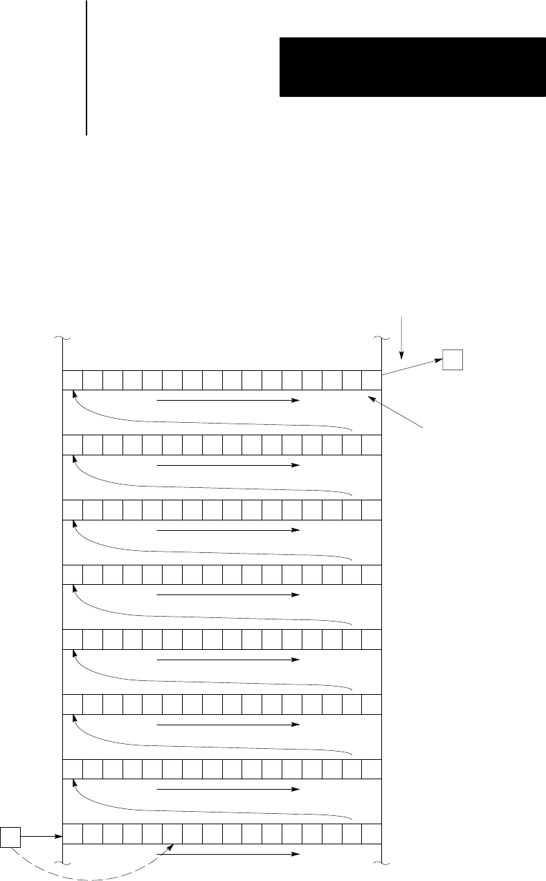
The Bit Shift Right output instruction constructs a synchronous bit shift
register from 1 to 999 bits in length. Figure 20.4 shows a 128 bit register
starting and ending at words 400 and 407.
Figure 20.4
How
the Processor Shifts a Bit to the Right
16 151413121110987654321
R
R
32 17
R
R
48 33
R
R
64 49
R
R
80 65
R
R
96 81
R
R
112 97
R
R
128 113
R
127 123
6667
17 16 15 14 13 12 11 10 07 06 05 04 03 02 01 00
Bit Address
Input Bit B
Word Address
Output Bit A
Bit one of
Bit Shift Register
400
401
402
403
404
405
406
407
10387-I
Bit Shift Right