
User Manual Owner's manual
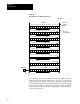
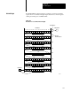
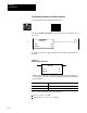
Table Of Contents
- 1772-6.5.8, Mini-PLC-2/02, -2/16, -2/17 Processor, User Manual
- Important User Information
- Summary of Changes
- Table of Contents
- 1 - Using This Manual
- 2 - Fundamentals of a Programmable Controller
- 3 - Hardware Features
- 4 - Installing Your Programmable Controller
- 5 - Starting Your Processor
- 6 - Maintaining and Troubleshooting Your Processor
- 7 - Memory Organization
- 8 - Scan Theory
- 9 - Relay-Like Instructions
- 10 - Program Control Instructions
- 11 - Timers and Counters
- 12 - Data Manipulation and Compare Instructions
- 13 - Three-Digit Math Instructions
- 14 - EAF Math Instructions
- 15 - EAF Log, Trig, and FIFO Instructions
- 16 - EAF Process Control Instructions
- 17 - Jump Instructions and Subroutines
- 18 - Block Transfer
- 19 - Data Transfer Instructions
- 20 - Bit Shift Registers
- 21 - Sequencers
- 22 - Selectable Timer Interrupts
- 23 - Report Generation
- 24 - Program Editing
- 25 - Programming Techniques
- 26 - Program Troubleshooting
- A - Specifications
- B - Processor Comparison Chart
- C - Number Systems
- D - Glossary
- E - Quick Reference
- Index
- Back Cover

Bit Shift Registers
Chapter 20
20-2
Figure 20.1
How
the Processor Shifts a Bit to the Left
16 151413121110987654321
L
32 17
L
48 33
L
64 49
L
80 65
L
96 81
L
112 97
L
128 113127 123
6667
17 16 15 14 13 12 11 10 07 06 05 04 03 02 01 00
Bit Address
Output Bit B
Word Address
Input BIt A
Bit one of
Bit Shift Register
400
401
402
403
404
405
406
407
10386-I
L
L
L
L
L
L
L
L
Upon false-true-rung transition, input bit A from a particular input word
shifts into the first bit of the bit shift register. Bit 1 moves to the left and
displaces bit 2; bit 2 displaces bit 3; and so on. Each bit displaces the one
to its left until the last bit in the word (bit 16) is reached. Bit 16 displaces
bit 17, which is really bit 1 of the next word (in this example, bit 401/00).
Bumping continues throughout the file until last bit is ejected from the
queue into output bit B.