
User Manual Owner's manual
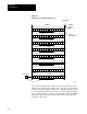
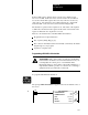
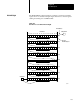
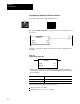
Table Of Contents
- 1772-6.5.8, Mini-PLC-2/02, -2/16, -2/17 Processor, User Manual
- Important User Information
- Summary of Changes
- Table of Contents
- 1 - Using This Manual
- 2 - Fundamentals of a Programmable Controller
- 3 - Hardware Features
- 4 - Installing Your Programmable Controller
- 5 - Starting Your Processor
- 6 - Maintaining and Troubleshooting Your Processor
- 7 - Memory Organization
- 8 - Scan Theory
- 9 - Relay-Like Instructions
- 10 - Program Control Instructions
- 11 - Timers and Counters
- 12 - Data Manipulation and Compare Instructions
- 13 - Three-Digit Math Instructions
- 14 - EAF Math Instructions
- 15 - EAF Log, Trig, and FIFO Instructions
- 16 - EAF Process Control Instructions
- 17 - Jump Instructions and Subroutines
- 18 - Block Transfer
- 19 - Data Transfer Instructions
- 20 - Bit Shift Registers
- 21 - Sequencers
- 22 - Selectable Timer Interrupts
- 23 - Report Generation
- 24 - Program Editing
- 25 - Programming Techniques
- 26 - Program Troubleshooting
- A - Specifications
- B - Processor Comparison Chart
- C - Number Systems
- D - Glossary
- E - Quick Reference
- Index
- Back Cover

Chapter
20
20-1
Bit Shift Registers
This chapter describes bit shift instructions. The bit shift instructions are:
The Bit Shift Left or Right instructions move one bit to the left or right
upon the false-true transition of a rung. They are output instructions
that construct and manipulate a synchronous bit shift register from
1-999 bits in length. You can perform these operations only in the
complete mode.
The Examine Off or Examine On Bit Shift instructions are condition
instructions that examine bits in a shift register. You can specify the bit
number to be examined and the starting address of the shift register.
Bit Shift Set and Reset Bit Shift are output instructions that set or reset a
specified bit in a bit shift register. You can specify the bit number to be
manipulated and the starting address of the shift register.
The Bit Shift Left output instruction constructs a synchronous bit shift
register from 1-999 bits in length. Figure 20.1 shows a 128-bit register
starting and ending at words 400 and 407.
Chapter Objectives
Bit Shift Left