
User Manual Owner's manual
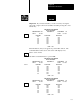
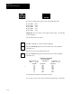
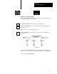
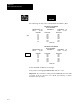
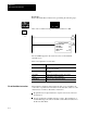
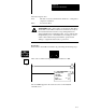
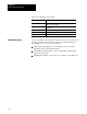
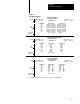
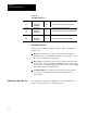
Table Of Contents
- 1772-6.5.8, Mini-PLC-2/02, -2/16, -2/17 Processor, User Manual
- Important User Information
- Summary of Changes
- Table of Contents
- 1 - Using This Manual
- 2 - Fundamentals of a Programmable Controller
- 3 - Hardware Features
- 4 - Installing Your Programmable Controller
- 5 - Starting Your Processor
- 6 - Maintaining and Troubleshooting Your Processor
- 7 - Memory Organization
- 8 - Scan Theory
- 9 - Relay-Like Instructions
- 10 - Program Control Instructions
- 11 - Timers and Counters
- 12 - Data Manipulation and Compare Instructions
- 13 - Three-Digit Math Instructions
- 14 - EAF Math Instructions
- 15 - EAF Log, Trig, and FIFO Instructions
- 16 - EAF Process Control Instructions
- 17 - Jump Instructions and Subroutines
- 18 - Block Transfer
- 19 - Data Transfer Instructions
- 20 - Bit Shift Registers
- 21 - Sequencers
- 22 - Selectable Timer Interrupts
- 23 - Report Generation
- 24 - Program Editing
- 25 - Programming Techniques
- 26 - Program Troubleshooting
- A - Specifications
- B - Processor Comparison Chart
- C - Number Systems
- D - Glossary
- E - Quick Reference
- Index
- Back Cover
Data Transfer File Instruction
Chapter 19
19-18
Table 19.B
Data Monitor Functions
Display
Print
[DISPLAY] [0]
[DISPLAY] [0]
[RECORD]
Any
Any
Displays the binary data monitor
Prints the first 20 lines of binary data monitor.
Display
Print
[DISPLAY] [1]
[DISPLAY] [1]
[RECORD]
Any
Any
Displays the hexadecimal data monitor
Prints the first 20 lines of hexadecimal data monitor.
Display
Print
[DISPLAY] [2]
[DISPLAY] [2]
[RECORD]
Any
Any
Displays the ASCII data monitor
Prints the first 20 lines of ASCII data monitor.
Data Monitor Functions
Three sections divide the data monitor display. They are identified in
(Figure 19.3):
Header: located at the top of the screen and contains information
pertaining to its corresponding file instruction. For example: counter,
file, and word addresses, also file length.
File Section: located in the center of the screen and displays the data
stored in a file. The column labeled POSITION refers to each word’s
position in the file. FILE A DATA represents the source file, and FILE
R DATA represents the destination file.
Command Buffer: located at the bottom center of the screen and is
used to enter or change file data. It is always displayed in the
program mode.
You may have to expand your data table to provide additional space for
files. To do this, follow the procedure in chapter 7.
Adjusting the Data Table Size